Automatic corrugated pipe welding equipment for transformer and welding method thereof

An automatic welding and corrugated tube technology, which is applied in welding equipment, arc welding equipment, metal processing equipment, etc., can solve the problem that it is difficult to meet the real-time and precision requirements of the automatic welding process, the image processing process is cumbersome, and the automatic welding of bellows for transformers is not easy. Too applicable and other issues, to achieve the effect of friendly operation interface, rich functions, and real-time calculation

Inactive Publication Date: 2012-06-06
SHENYANG INST OF AUTOMATION - CHINESE ACAD OF SCI
View PDF8 Cites 20 Cited by
  • Summary
  • Abstract
  • Description
  • Claims
  • Application Information

AI Technical Summary

Problems solved by technology

[0004] Most of the current automatic welding equipment adopts non-contact CCD image sensing system to obtain the image information near the weld seam, and then the computer performs image processing to obtain the control information required for weld seam tracking. The image processing process of this method is relatively It is cumbersome, and it is difficult to meet the real-time and precision requirements of the automatic welding process, so it is not suitable for automatic welding of bellows for transformers

Method used


Image

  • Automatic corrugated pipe welding equipment for transformer and welding method thereof
  • Automatic corrugated pipe welding equipment for transformer and welding method thereof
  • Automatic corrugated pipe welding equipment for transformer and welding method thereof

Examples


Embodiment 1

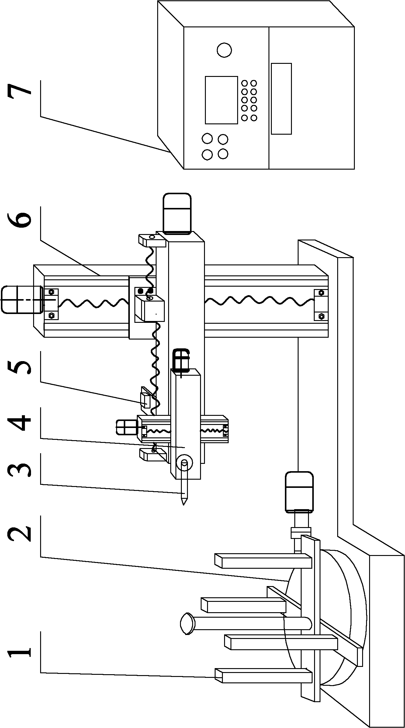
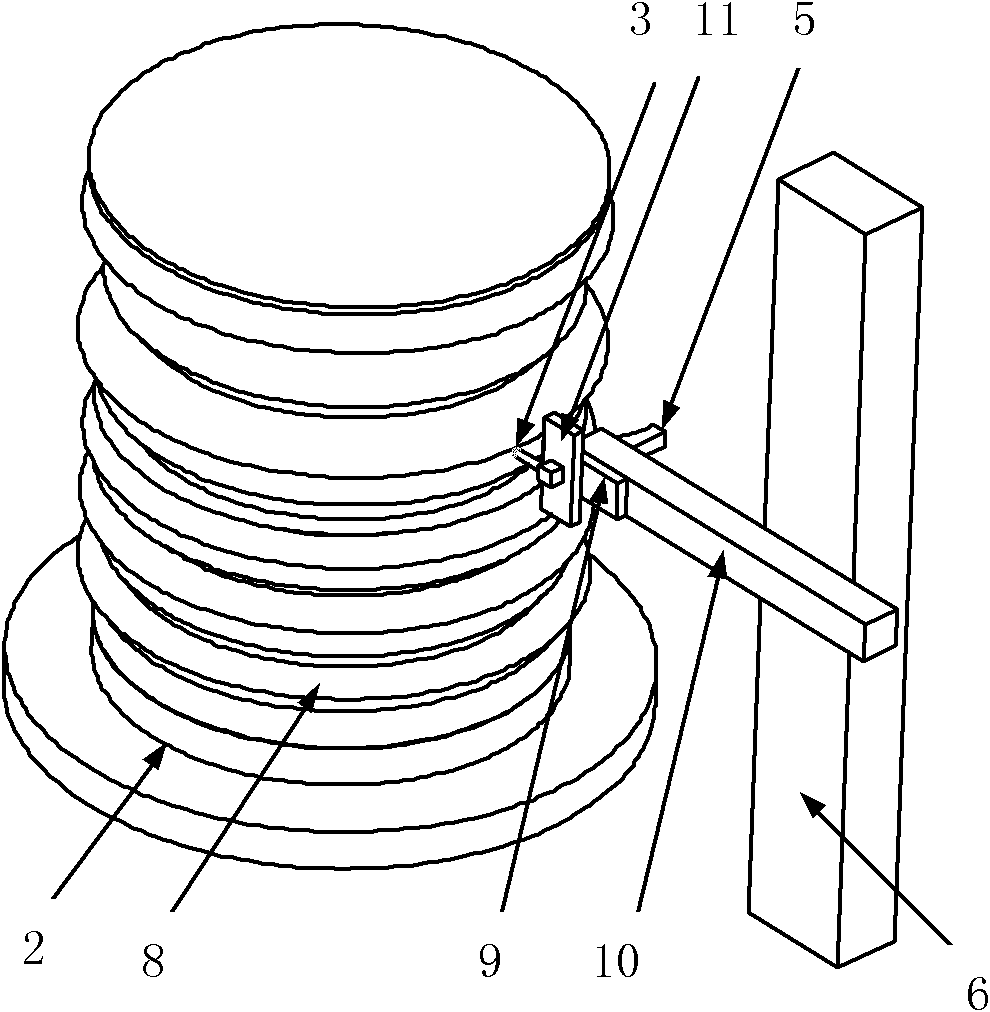
[0036] Embodiment 1: For corrugated pipes of different specifications, the welding torch used as the welding device must have 5 degrees of freedom to meet the requirements of the working position. Therefore, if figure 1 As shown, the present invention includes a rotary table 2, a two-dimensional numerical control platform 4, a laser profile measuring instrument 5, an R-axis 10 and a welding machine tool. The rotary table 2 is fixed on the working table of the machine tool, and one end of the R-axis 10 is slidingly installed on On the bed 6 of the welding machine tool, a laser profile measuring instrument 5 and a two-dimensional numerical control platform 4 sliding along the R axis 10 are respectively installed on both sides of the other end, and a welding torch 3 is slidably connected to the two-dimensional numerical control platform. The laser of the instrument 5 is parallel to the axis of the welding torch 3, the rotary table 2, the two-dimensional numerical control platform...


PUM


Abstract

The invention relates to automatic corrugated pipe welding equipment for a transformer and a welding method thereof, and belongs to the welding technical field of a corrugated pipe for a transformer. The automatic corrugated pipe welding equipment for the transformer comprises a rotary workbench, a two-dimensional numerical control platform, a laser outline measuring instrument, an R axis, a welding machine tool and a control system; the rotary workbench is fixed on the workbench surface of the machine tool; one end of the R axis is arranged on the welding machine tool body in a sliding way, and both sides of the other end of the R axis are respectively provided with the laser outline measuring instrument and the two-dimensional numerical control platform which slides along the R axis; a welding torch is connected onto the two-dimensional numerical control platform in a sliding way; the laser of the laser outline measuring instrument is in parallel with the axis of the welding torch; the rotary workbench, the two-dimensional numerical control platform and the welding machine tool body are respectively connected with the controller of the control system through motors; and the laser outline measuring instrument is connected with the industrial computer of the control system. The automatic corrugated pipe welding equipment for the transformer and the welding method thereof solvethe difficult problem of the manual welding of a large thin-wall corrugated pipe, reduce the labor intensity of a welder, improve the production efficiency, and simultaneously ensure the uniformity and the stability of the welding quality.

Description

technical field [0001] The invention belongs to the technical field of welding bellows used in transformers, and relates to a welding equipment and method for bellows used in transformers. Background technique [0002] Metal bellows have the characteristics of corresponding displacement under the action of pressure, axial force, lateral force or bending moment, and have many advantages such as pressure resistance, vacuum sealing, corrosion resistance, temperature stability and long service life. Therefore, it is more and more widely used in the field of transformers. [0003] In production practice, the bellows for transformers are formed by welding multi-section bellows and support rings, and are often welded together with other components (such as flanges, etc.) to form bellows components. The axial and radial deviations of the bellows components are more than 20 mm, and the welding quality is difficult to guarantee. The traditional manual welding process has disadvantag...

Claims


Application Information

Patent Timeline
Patent Type & Authority Applications(China)
IPC IPC(8): B23K9/02B23K9/127B23K9/095
Inventor 刘伟军李论王静于彦凤乔红超
Owner SHENYANG INST OF AUTOMATION - CHINESE ACAD OF SCI
Why Eureka
Try Eureka