Supercharge Your Innovation With Domain-Expert AI Agents!

Up-flow multilayer sludge bed treatment device

A technology of treatment device and sludge bed, applied in the field of sludge treatment device, can solve the problems of waste of effective sludge storage volume, unfavorable sludge disposal method, large area of ​​facilities, etc., so as to increase biological load and pollution. The effect of sludge digestion ability, improving sludge treatment ability and prolonging residence time

Inactive Publication Date: 2012-06-06
赵峰
View PDF0 Cites 0 Cited by
  • Summary
  • Abstract
  • Description
  • Claims
  • Application Information

AI Technical Summary

Problems solved by technology

[0002] The by-product of sewage treatment is sludge, and improper treatment of sludge will cause secondary pollution
Under the principles of sludge reduction, stabilization, and harmlessness, sludge generally needs to be treated and disposed of. Commonly used methods include dehydration, concentration, digestion, and drying. However, sludge undergoes this stage. After treatment, the moisture content is still high and the volume is large, which is not conducive to the subsequent sludge disposal method
From the perspective of common sense logic, as long as there are large enough containers or facilities to store and digest sludge, the impact of sludge on the environment can be reduced, but such facilities occupy too much area
If you want to improve the capacity of the facility to store sludge, you need to increase the volume of the facility from both the plane area and the height. Only increasing the height of the facility will cause a waste of effective volume for storing sludge. Therefore, it is necessary to design a In the case of increasing the height of the facility, it can still ensure the increase of the settlement area, can make full use of the effective volume of the facility, can store and digest sludge, and ensure good working efficiency.

Method used


Image

  • Up-flow multilayer sludge bed treatment device
  • Up-flow multilayer sludge bed treatment device
  • Up-flow multilayer sludge bed treatment device

Examples


Embodiment Construction

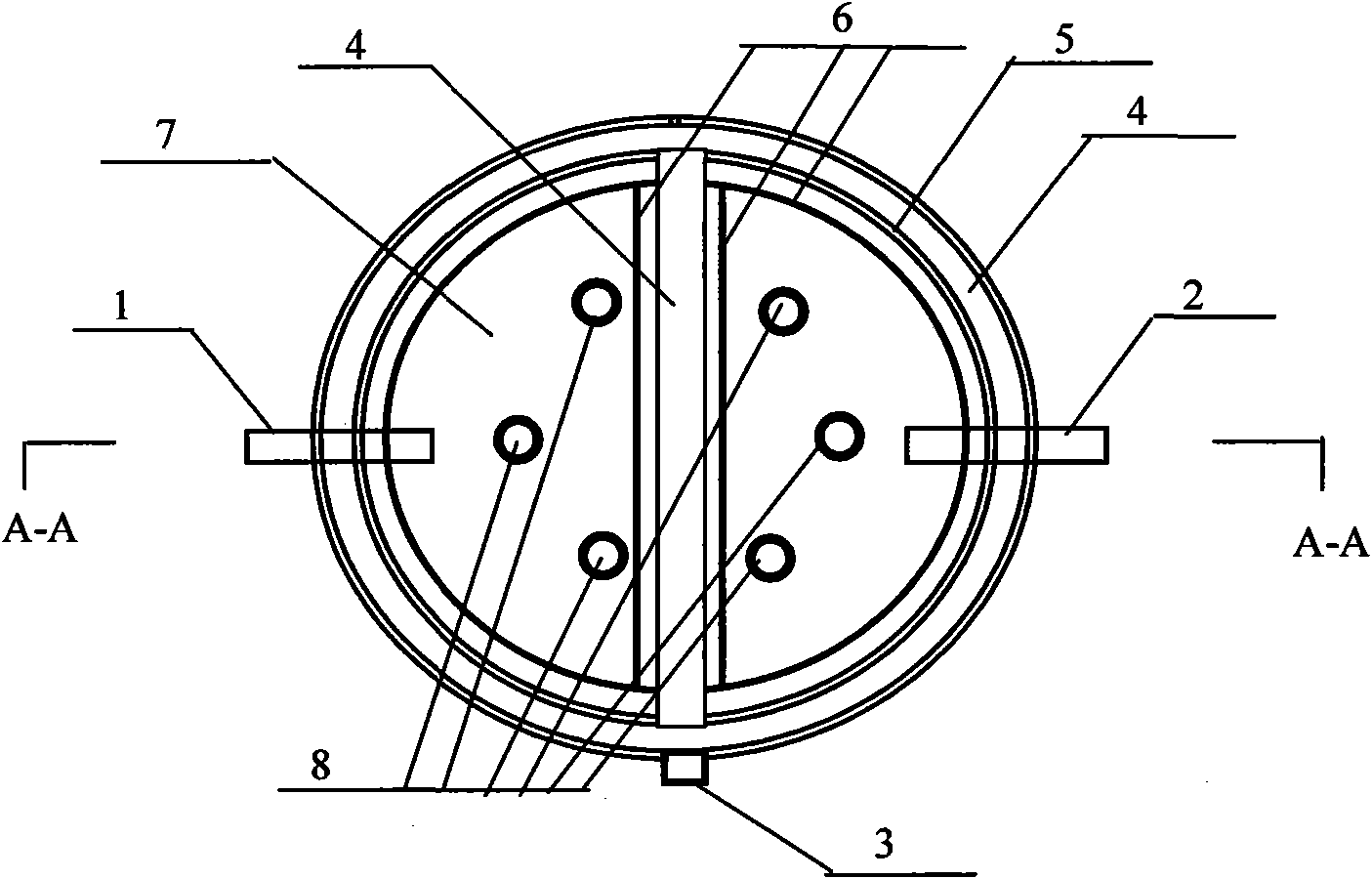
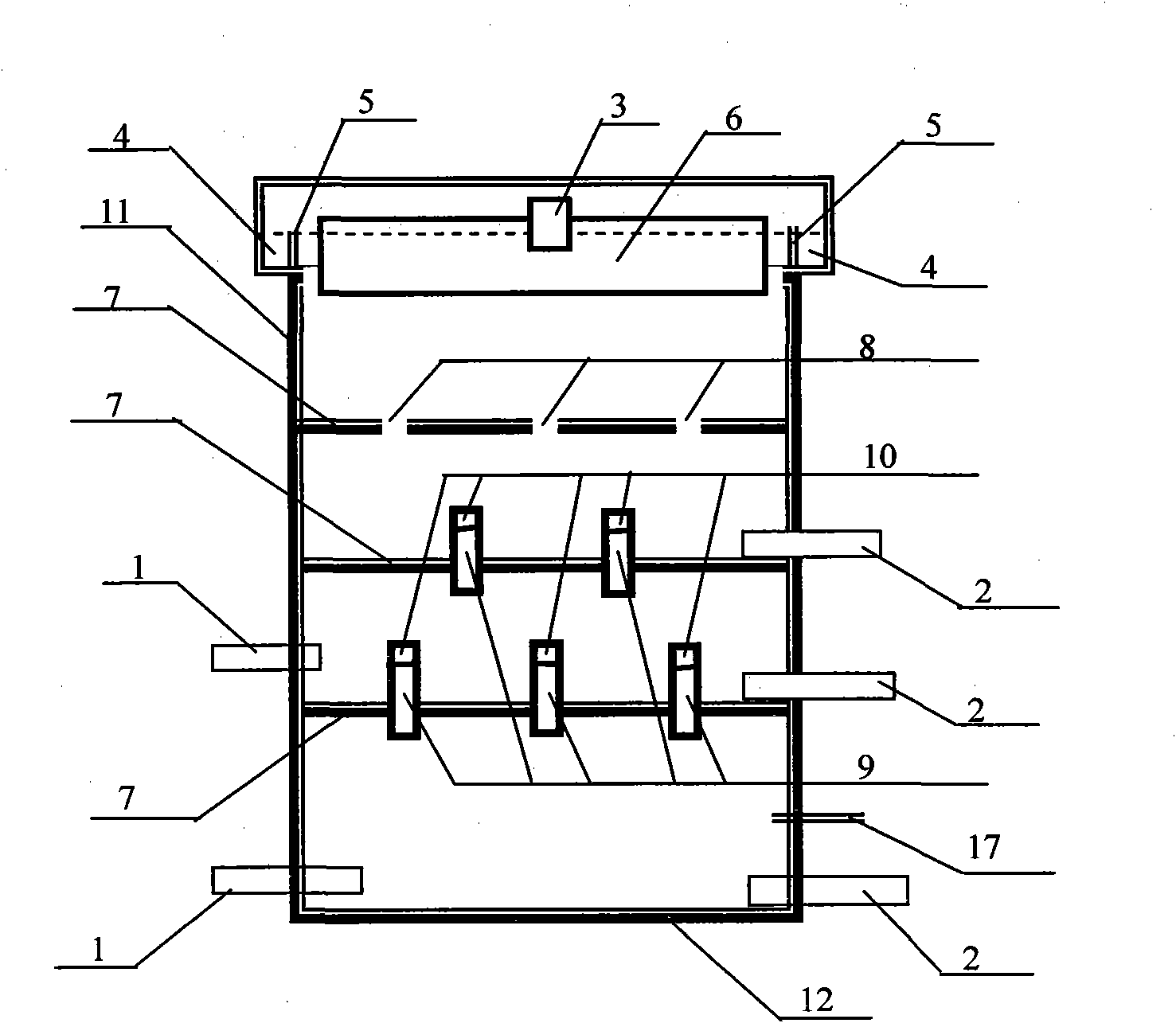
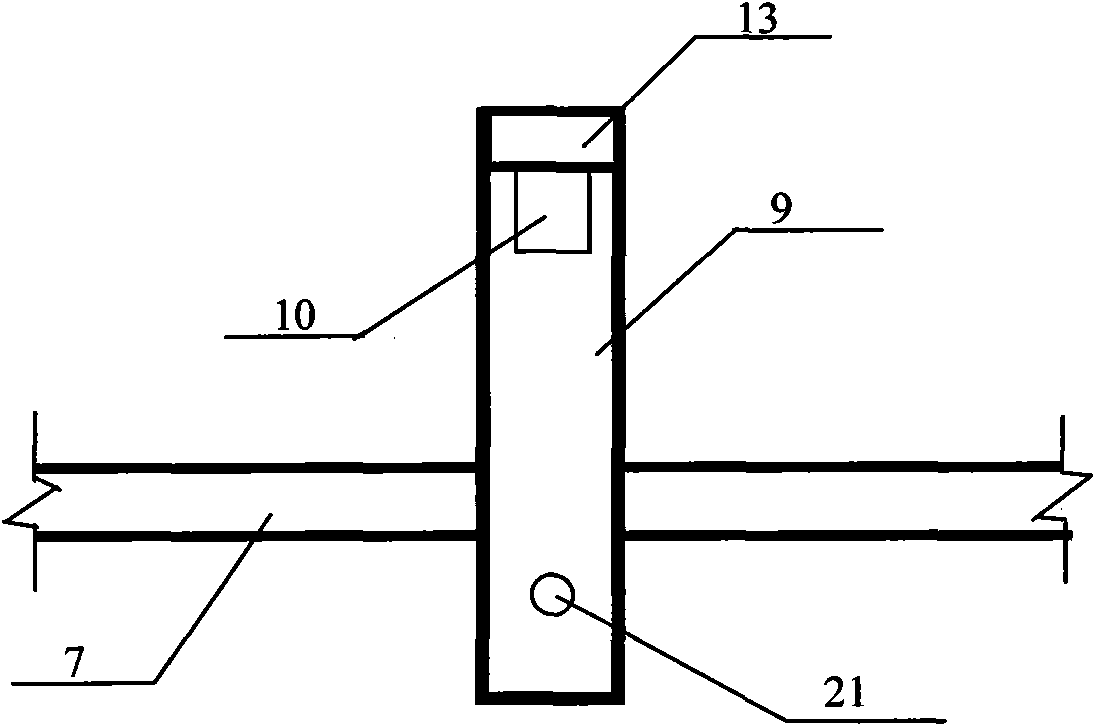
[0014] like figure 1 , 2 The first scheme shown in 3 and 3 is a cylindrical up-flow sludge treatment device with an open top surface of the tank body. The tank body adopts a reinforced concrete structure. The bottom of the tank is a flat tank bottom 12. 7 is divided into four pool spaces, the uppermost layered floor 7 is provided with a plurality of water passage openings 8, and the lower two layered floor plates 7 are provided with a plurality of space through water distribution pipes 9, and the space through the water distribution pipe 9. There is a radial outlet 10, the upper part of the radial outlet 10 is a through-pipe top cover 13, there is at least one ventilation hole 21 on the through-tube 9 in the space below the layered floor 7, and at least one mud water inlet pipe is installed on the side wall 11 of the pool body. 1. Each layer of the pool space with sludge deposition is provided with a sludge discharge pipe 2, and a collection channel groove 4 is arranged aroun...


PUM


Abstract

The invention provides an up-flow multilayer sludge bed treatment device, which is mainly characterized in that: the inside of a tank body is divided into four tank spaces by layering floorslabs 7, the top layering floorslab is provided with a plurality of water passing openings 8, while the lower two layering floorslabs are equipped with multiple space run-through distribution pipes 9, which are provided with radial flow openings 10, above which run-through pipe top caps 13 are positioned, and the space run-through pipes 9 below the layering floorslabs 7 are equipped with at least one air vent 21, at least one muddy water inlet pipe 1 is installed on the side wall 11 of the tank body, each layer of tank space with sludge sediment is equipped with a sludge discharge pipe 2, water collection channels 4 are disposed around the top of the tank body and in the tank, and effluent weirs 5 are arranged at the water collection channels 4, flow baffles 6 are positioned in front of the effluent weirs 5, the water collection channel 4 at the tank top is provided with a water outlet 3 outwards, and the tank wall 11 is equipped with a detection pipe 17. While digesting sludge, the device of the invention can store sludge, prolong the retention period of sludge, and realize stabilization and reduction of sludge treatment.

Description

technical field [0001] The invention relates to a sludge treatment device. Background technique [0002] The by-product of sewage treatment is sludge, and improper treatment of sludge will cause secondary pollution. Under the principle of reduction, stabilization and harmlessness of sludge treatment, sludge is generally treated and disposed of. Commonly used methods include dehydration, concentration, digestion, drying and other treatment methods, but the sludge passes through this stage. After treatment, the water content is still high and the volume is large, which is not conducive to the subsequent sludge disposal method. From the point of view of common sense logic, as long as there are large enough containers or facilities to store and digest sludge, the impact of sludge on the environment can be reduced, but such facilities take up too much space. If you want to improve the facility's ability to store sludge, it is necessary to increase the volume of the facility fro...

Claims


Application Information

Patent Timeline
IPC IPC(8): C02F11/04C02F11/12C02F11/00
Inventor 赵峰
Owner 赵峰
Features
  • R&D
  • Intellectual Property
  • Life Sciences
  • Materials
  • Tech Scout
  • Unparalleled Data Quality
  • Higher Quality Content
  • 60% Fewer Hallucinations
Learn More