Spraying apparatus, paving machine, and construction method of liquid-state asphalt

A liquid asphalt and paver technology, which is applied in the field of asphalt paver and asphalt spraying, can solve the problem that the walking speed of the paver does not match the spraying speed, the asphalt storage tank and the sprinkler are not circulating pipelines, and they are easy to accumulate and accumulate. Blocking nozzles or pipes, etc., to achieve the effect of improving the quality of paving, taking up less space and having a high degree of automation

Inactive Publication Date: 2012-06-13
SHAANXI CHANGDA INDAL
View PDF7 Cites 14 Cited by
  • Summary
  • Abstract
  • Description
  • Claims
  • Application Information

AI Technical Summary

Problems solved by technology

[0006] The above two kinds of laterally moving asphalt spraying devices adopt the method of laterally moving and spraying relative to the forward direction of the paver. Although the problem of incompatibility between the walking speed of the paver and the spraying speed is solved, there is no circulation pipe between the asphalt storage tank and the spray head. Road, after a horizontal spraying, the nozzle is turned off, and the next spraying is performed after moving back to the original position. Because the asphalt material has high temperature requirements, it is easy to accumulate and block the nozzle or pipe after cooling, thus affecting the spraying

Method used


Image

  • Spraying apparatus, paving machine, and construction method of liquid-state asphalt
  • Spraying apparatus, paving machine, and construction method of liquid-state asphalt
  • Spraying apparatus, paving machine, and construction method of liquid-state asphalt

Examples


Embodiment 1

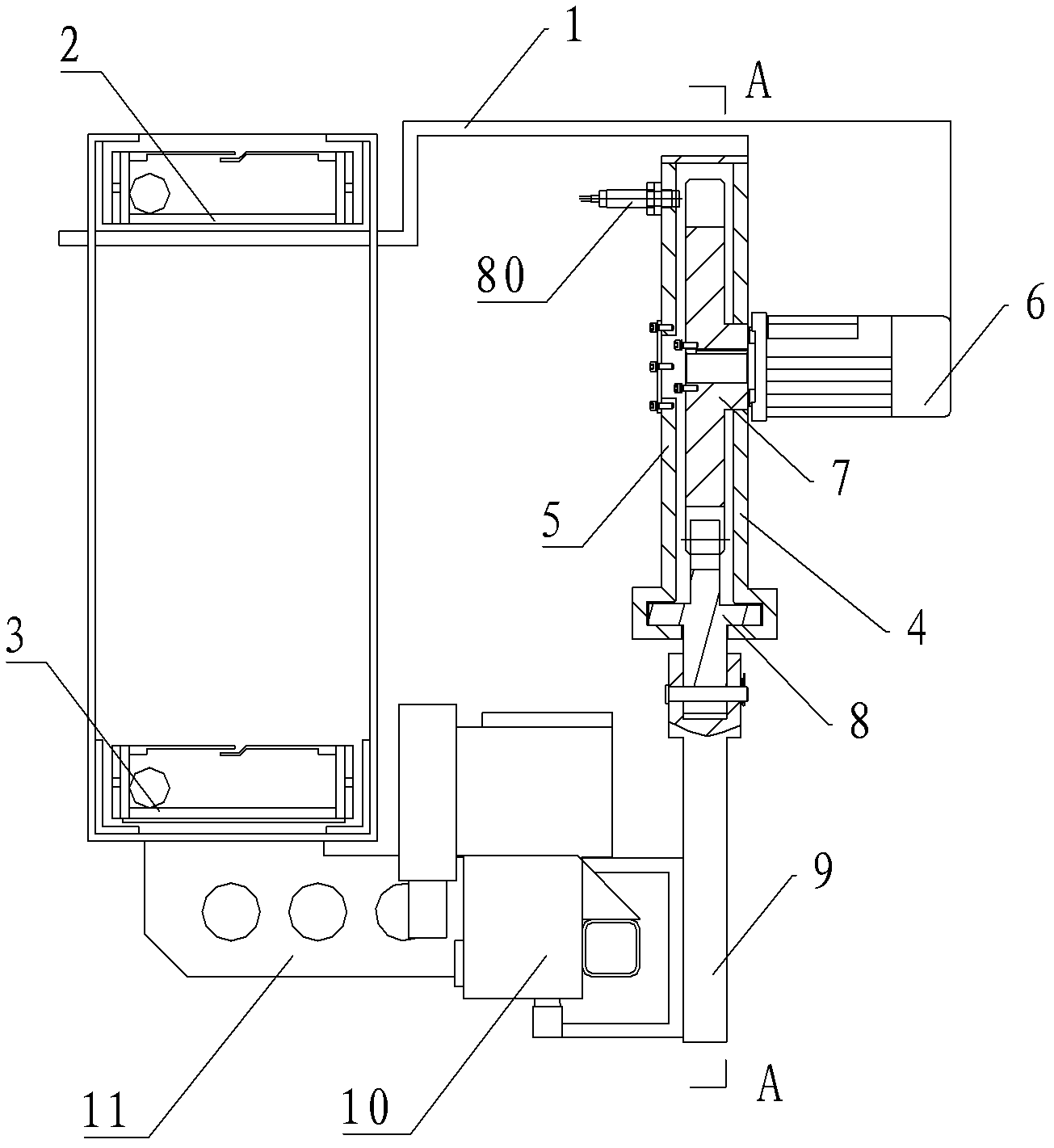
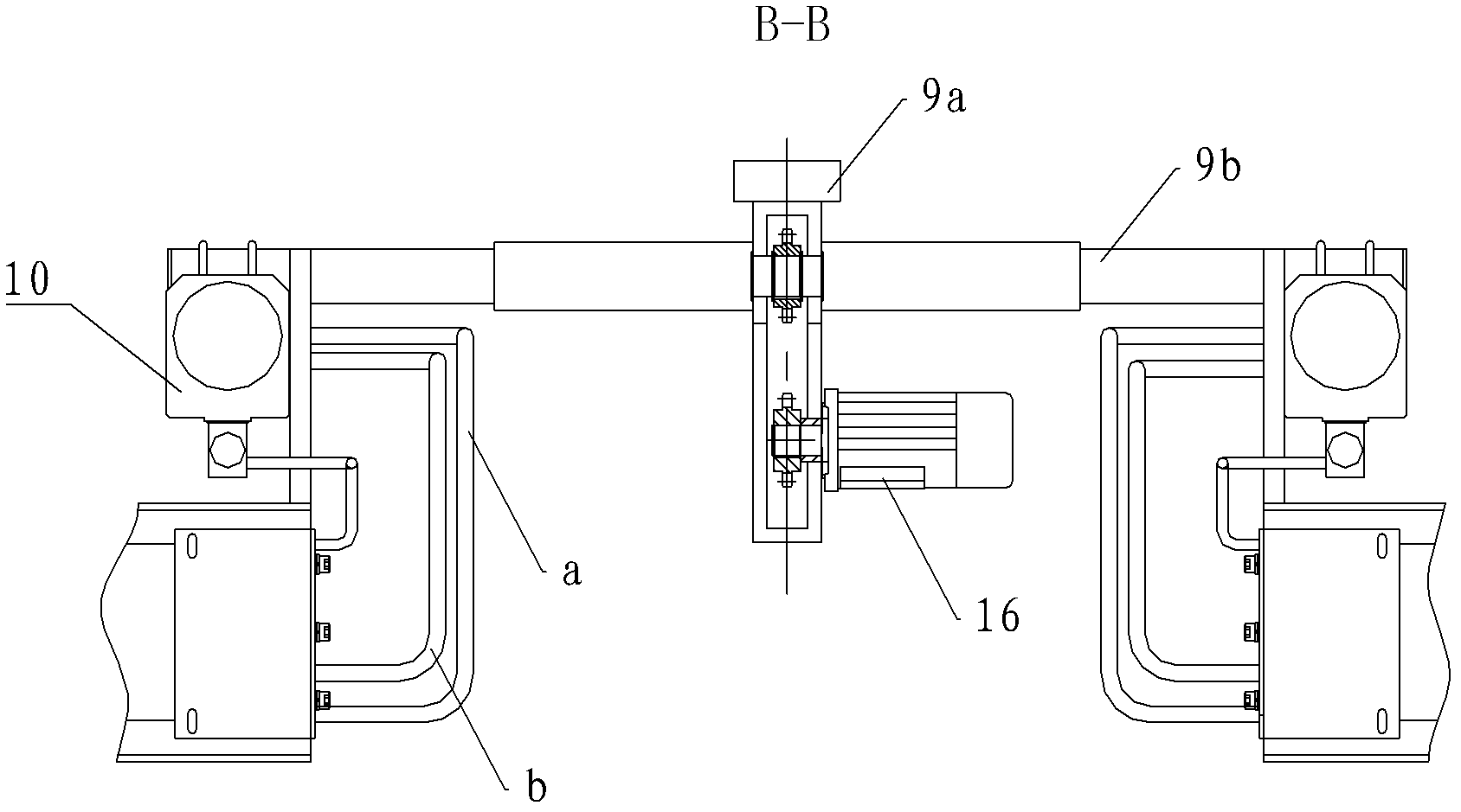
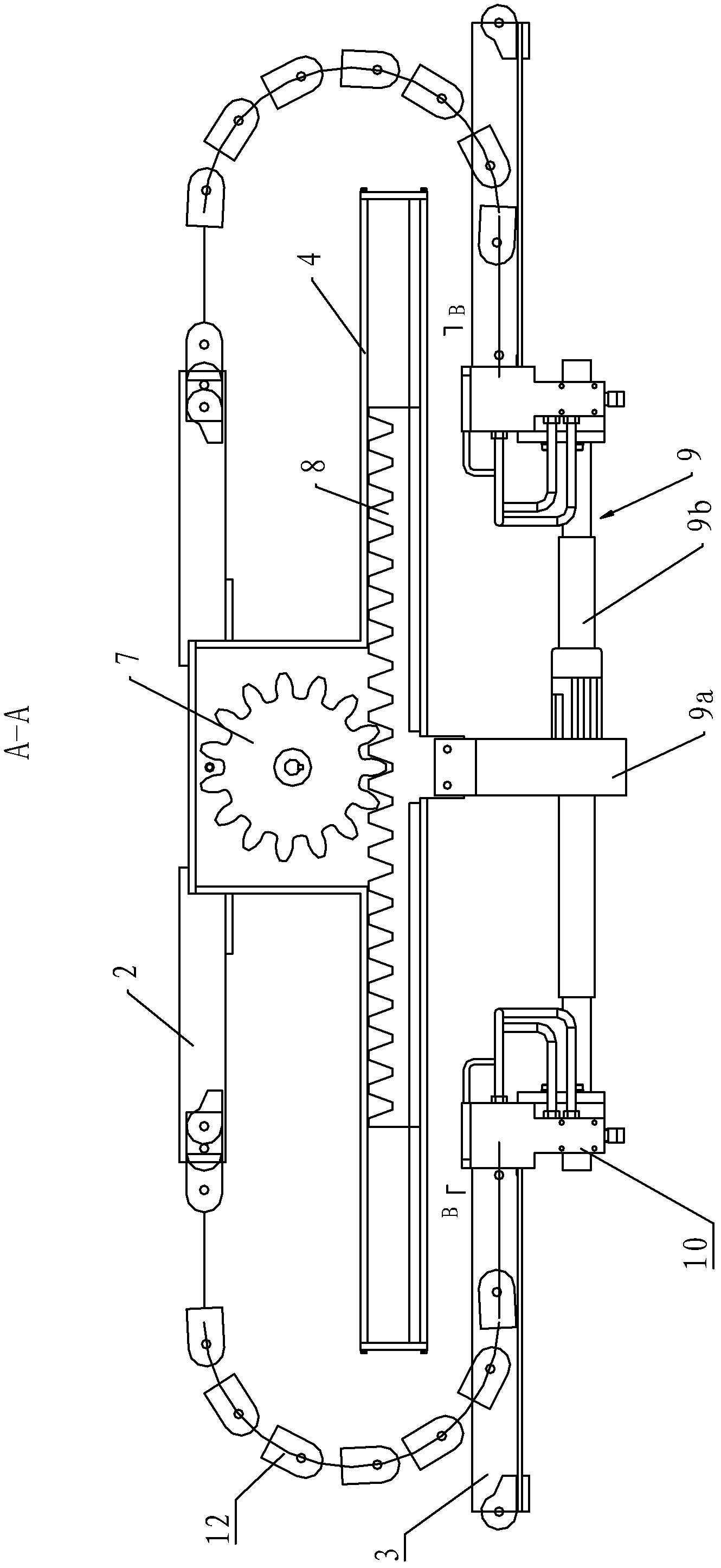
[0036] Such as figure 1 , figure 2 and image 3 As shown, the asphalt spreading device of this embodiment includes a mounting plate 1, an upper drag chain frame 2, a lower drag chain frame 3, a gear box 4, a round end cover 5, a motor 6, a gear 7, a rack 8, and a carriage 9 , Nozzle 10, fixed plate 11, drag chain 12. For convenience of description, the direction parallel to the rack 7 is defined as the transverse direction.

[0037] The asphalt spreading device of the present invention is fixedly installed on the asphalt paver through the mounting plate 1, and is located at the rear of the paver body, before the distribution screw, and is used for spraying liquid asphalt or other liquid emulsified adhesives to the ground. The tooth box 4 is fixed to the mounting plate 1, and relative to the spray head, the tooth box 4 is a fixing frame of the present invention. The tooth box 4 of this embodiment is ⊥-shaped, and a chute (not labeled) is provided at the bottom of the tooth...

Embodiment 2

[0044] Such as Figure 5 and Figure 6 As shown, the difference between this embodiment and Embodiment 1 is that the mobile driving mechanism of this embodiment is a hydraulic cylinder 106, and the hydraulic cylinder 106 is arranged under the gear box 4, one end is fixed on the gear box 4, and the other end is fixed on the On the slide frame 9, the hydraulic cylinder 106 can move the slide frame 9 left and right, and a linear displacement sensor 80 is installed at the bottom of the gear box 4 to determine the displacement and speed of the transmission slide frame. In this embodiment, the hydraulic cylinder 106 is installed under the outside of the gear box 4 . The hydraulic cylinder 106 can also be installed in the gear box 4 , and one end is fixedly connected with the carriage 9 to realize the movement control of the carriage 9 .

Embodiment 3

[0046] Such as Figure 7 and Figure 8 As shown, the difference between this embodiment and Embodiment 1 is that a screw rod 208 equal in length to the gear box 204 is installed in the gear box 204, and a threaded sleeve 207 is installed on the screw rod 208, and the screw sleeve 207 and the slide frame 9 Fixed installation, the motor 6 is installed on one end of the gear box 204, the motor 6 is connected with the screw mandrel 208 through the transmission mechanism, and drives the screw mandrel 208 to rotate, so that the screw sleeve 207 moves laterally on the screw mandrel 208, when the screw mandrel 208 is forward / reverse When rotating, the screw sleeve 207 makes linear reciprocating motion. A linear displacement sensor 80 is installed at the bottom of the gear box 204 to determine the displacement and speed of the screw sleeve.


PUM


Abstract

The invention relates to a spraying apparatus, a paving machine, and a construction method of liquid-state asphalt. The asphalt spraying apparatus is arranged on a body of the paving machine through an installation frame. The asphalt spraying apparatus is arranged on the rear part of the paving machine, and in front of a material-distributing screw. The asphalt spraying apparatus comprises a fixed frame, a slide frame, a spraying nozzle, and a driving apparatus. An inflow pipeline, a backflow pipeline, a spraying pipeline, and controlling valves which with the pipelines communicate with each other are arranged in the spraying nozzle. A speed measuring sensor used for determining a sideslip speed and a displacement of the slide frame is arranged on the fixed frame. The spraying nozzle is connected with an asphalt input pipe through an asphalt inlet pipe, and is connected with an asphalt backflow pipe through an asphalt outlet pipe. The asphalt input pipe and the asphalt backflow pipe communicate with an asphalt storing tank. An asphalt pump and a gas/liquid controlling valve are arranged on an input end of the asphalt input pipe. The gas/liquid controlling valve is connected to an air compressor through a gas pipeline. The apparatus provided by the invention is advantaged in small land occupation, simple and compact structure, and high automation degree. With the spraying apparatus, during a paving machine low-speed paving procedure, the spraying nozzle is prevented from continuously spraying asphalt, such that a non-uniform paving phenomenon is avoided, and a paving quality is improved.

Description

technical field [0001] The invention belongs to the field of road construction machinery, and in particular relates to a laterally movable asphalt spreading device, an asphalt paver equipped with a mobile asphalt spreading device and an asphalt spreading method. Background technique [0002] Asphalt pavement is a pavement structure in which a certain thickness of asphalt mixture is paved on a flexible base or a semi-rigid base. Compared with gravel pavement, this kind of pavement has greatly improved driving comfort, safety and strength stability. Compared with cement concrete pavement, asphalt pavement has a smooth surface without joints, small driving vibration, low noise, and fast construction. Short construction period, fast open traffic, easy maintenance, suitable for phased construction of pavement, is an important structural form of pavement in our country. [0003] In the past, when building asphalt-stabilized soil pavements or pavement bases, it was necessary to us...

Claims


Application Information

Patent Timeline
Patent Type & Authority Applications(China)
IPC IPC(8): E01C19/17E01C19/48
Inventor 南文辉南希苟红侠
Owner SHAANXI CHANGDA INDAL
Why Eureka
Try Eureka