Method for monitoring intra-furnace dynamic wall temperature in high-temperature tube system of power station boiler

A technology for power station boilers and high-temperature tubes, which is applied to the indication of boiler working conditions, thermometer components, temperature measurement of moving fluids, etc. It is difficult to obtain the instrument, lack of modeling basis, accuracy and reliability, etc.

Active Publication Date: 2012-06-13
SHANGHAI WANGTE ENERGY RESOURCE SICENCE & TECH
View PDF5 Cites 19 Cited by
  • Summary
  • Abstract
  • Description
  • Claims
  • Application Information

AI Technical Summary

Problems solved by technology

[0010] The disadvantages of this technology are: (1) As stated in the subject of this patent application, it only performs intelligent wall temperature management on the two tube groups of the final stage superheater and the final stage reheater of the utility boiler, while the large-capacity boiler The reheater piping system of the superheater has a total of 6 tube groups, namely the first-stage superheater (or low-temperature superheater), the second-stage superheater (or partition superheater), and the third-stage superheater (rear screen superheater). ), four-stage superheater (ie final stage superheater), low-temperature reheater and high-temperature reheater
In the actual operation of the boiler, about 30-40% of the over-temperature explosion occurs in the primary superheater and the secondary superheater. This patent does not involve solving the over-temperature explosion of the two tube groups of the primary superheater and the secondary superheater (2) In step 1 and step 2 of the patented method, there is no technical solution and measure for the selection of the measurement collection points for obtaining monitoring data and their layout, the accuracy and reliability of the relationship measurement value, so all The calculation of steam temperature and wall temperature at the calculation point (monitoring point) in the furnace lacks basis and is difficult to meet the actual operating conditions of the boiler. If the measurement collection point is

Method used


Image

  • Method for monitoring intra-furnace dynamic wall temperature in high-temperature tube system of power station boiler
  • Method for monitoring intra-furnace dynamic wall temperature in high-temperature tube system of power station boiler
  • Method for monitoring intra-furnace dynamic wall temperature in high-temperature tube system of power station boiler

Examples


Embodiment

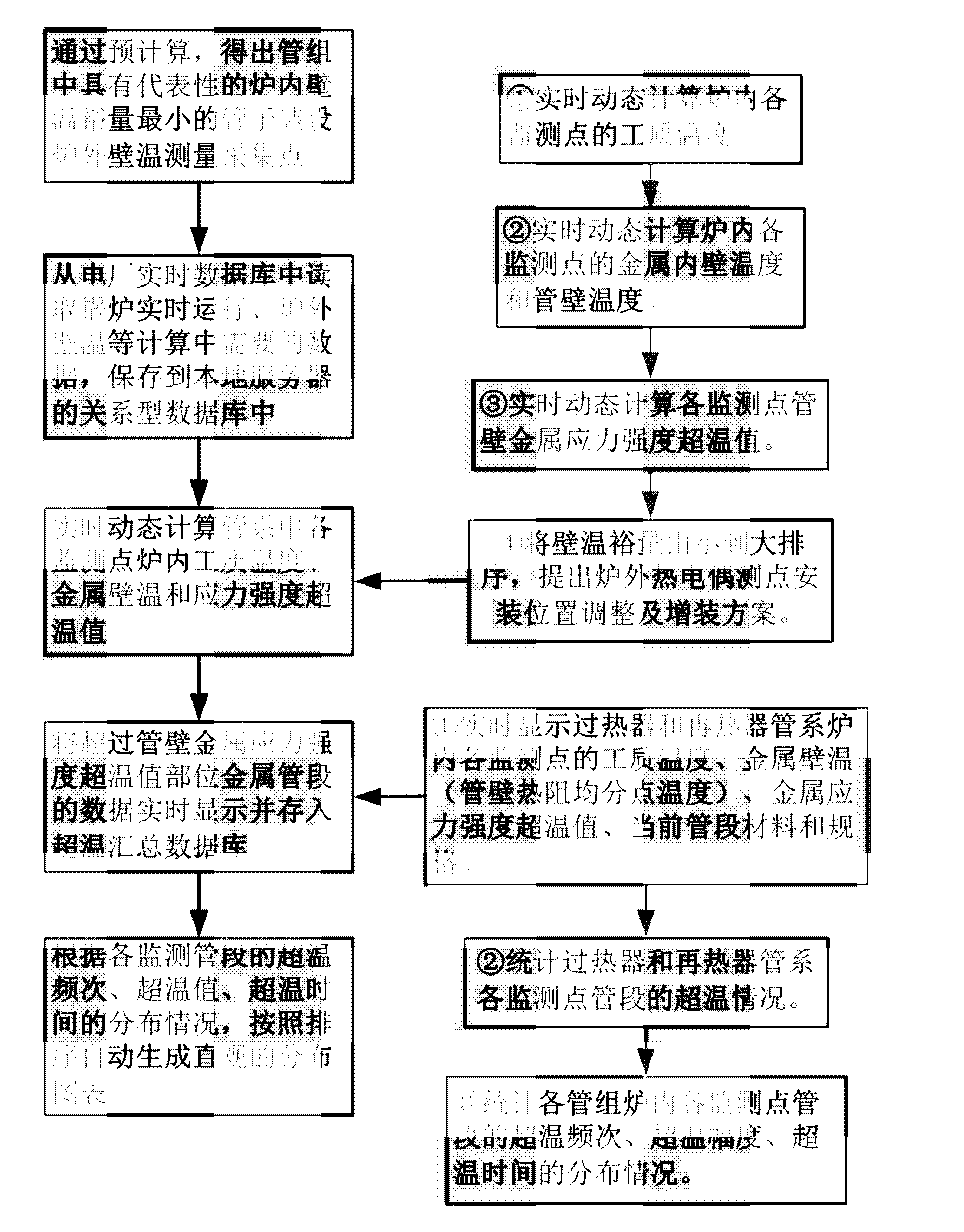
[0127] In this example, a 1000MW ultra-supercritical boiler in a power plant is selected, and the high-temperature reheater piping system adopts figure 1 The block schematic diagram of the implementation steps is shown.

[0128] This embodiment includes the following steps:

[0129] Step 1: Through pre-calculation, it is obtained that the typical temperature margin of the inner wall of the furnace in the piping system of the high-temperature reheater of the 1000MW ultra-supercritical boiler is installed to measure and collect the temperature of the outer wall of the furnace.

[0130] The high-temperature reheater of the 1000MW ultra-supercritical boiler has a total of 44 screens, and each screen has 24 tubes. A total of 1056 pipes are used to calculate 6336 pipe sections.

[0131] a. Calculate the enthalpy increase Δia of the pipe section

[0132] Δia=Kry(Q d +Q p +Q q +Q qq +Q z +Q h +Q x ) / ga

[0133] Where: Kr y The width endothermic deviation coefficient set fo...


PUM


Abstract

The invention discloses a method for monitoring intra-furnace dynamic wall temperature in a high-temperature tube system of a power station boiler in the technical field of the power station boilers. The method disclosed by the invention comprises the steps of: precomputing to obtain a representative tube with the minimal allowance of intra-furnace inner wall temperature in a tube group for installation of a furnace outer wall temperature measurement and collection point; reading data required for calculation of real-time operation of the boiler, the extra-furnace wall temperature and the like from a real-time database of a power plant, and storing the data in a relational database of a local server; generating real-time dynamic calculation of intra-furnace working medium temperature and intra-furnace metal wall temperature of a superheater and reheater tube system of the power station boiler according to real-time data of the real-time operation and the extra-furnace metal wall temperature; and separating the data of a metal tube section exceeding a tube wall metal stress intensity over-temperature value part and storing the data in an over-temperature summary database. The method disclosed by the invention effectively combines dynamic online calculation with dynamic online monitoring of practical working conditions so that the technical effect of prolonging the service life of the tube system is achieved and the technical problem on preventing over-temperature tube explosion of the tube system of the power station boiler is solved.

Description

technical field [0001] The invention relates to a method in the technical field of power plant boilers, in particular to a method for monitoring dynamic wall temperature in a high temperature tube system furnace of a power plant boiler. Background technique [0002] In recent years, with the rapid development of my country's power generation industry, a large number of supercritical and ultra-supercritical generating units have been put into operation, and parameters such as boiler grade, temperature, and pressure have been improved. At present, metal materials have been used close to the highest temperature-resistant grade, and the corresponding materials have smaller and smaller margins in terms of stress over-temperature. Many factors will cause over-temperature phenomena during operation, and also cause internal oxidation due to material over-temperature. The generation of the skin is too fast and falls off, causing problems such as plugging and bursting tubes. Boiler t...

Claims


Application Information

Patent Timeline
IPC IPC(8): F22B35/18F22B37/38
CPCF22B35/18F22B37/38G01K1/026G01K13/02
Inventor 王孟浩王衡
Owner SHANGHAI WANGTE ENERGY RESOURCE SICENCE & TECH
Why Eureka
Try Eureka