Temperature drift compensation optical current transformer and current compensation method thereof

A current transformer and temperature drift technology, applied in the field of transformers, can solve the problems of optical current transformer measurement accuracy temperature drift, etc.

Inactive Publication Date: 2012-06-13
HARBIN INST OF TECH +1
View PDF7 Cites 20 Cited by
  • Summary
  • Abstract
  • Description
  • Claims
  • Application Information

AI Technical Summary

Problems solved by technology

[0008] The purpose of the present invention is to solve the problem of tempe

Method used


Image

  • Temperature drift compensation optical current transformer and current compensation method thereof
  • Temperature drift compensation optical current transformer and current compensation method thereof
  • Temperature drift compensation optical current transformer and current compensation method thereof

Examples


specific Embodiment approach 1

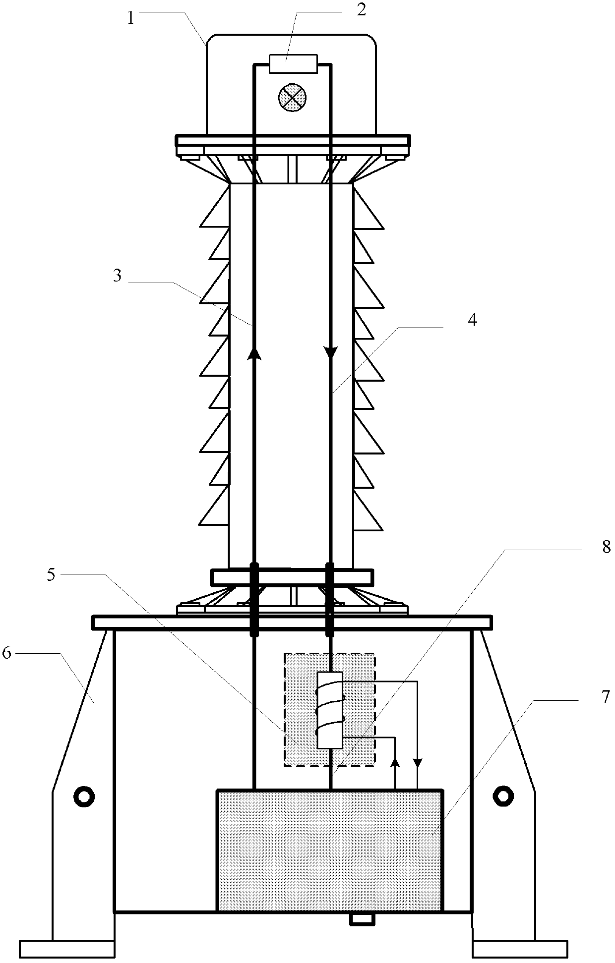
[0043]DETAILED DESCRIPTION OF THE PREFERRED EMBODIMENTS 1. A temperature drift compensation optical current transformer, which includes a housing 1, an optical sensor 2, a first multimode optical fiber 3, a polarization maintaining optical fiber 4, a base 6, a signal processing unit 7 and a second multimode optical fiber 8. The optical sensor 2 is fixed inside the casing 1, which is characterized in that it also includes a solenoid-type self-induction sensor 5,

[0044] One end of the optical sensor 2 is connected to one end of the solenoid-type self-inductance sensor 5 through a polarization-maintaining optical fiber 4, and the other end of the solenoid-type self-inductance sensor 5 is connected to the signal processing unit 7 through a second multimode optical fiber 8, and the optical sensor The other end of 2 is connected to the signal processing unit 7 through the first multimode optical fiber 3, the solenoid type self-inductance sensor 5 and the signal processing unit 7 ar...

specific Embodiment approach 2

[0048] Specific embodiment two, temperature drift current compensation method, it comprises the following steps:

[0049] Step 1. The Faraday rotation angle generated by the linearly polarized light of the optical sensor 2 according to the Faraday magneto-optical effect With the current to be measured i 1 Expressed as:

[0050]

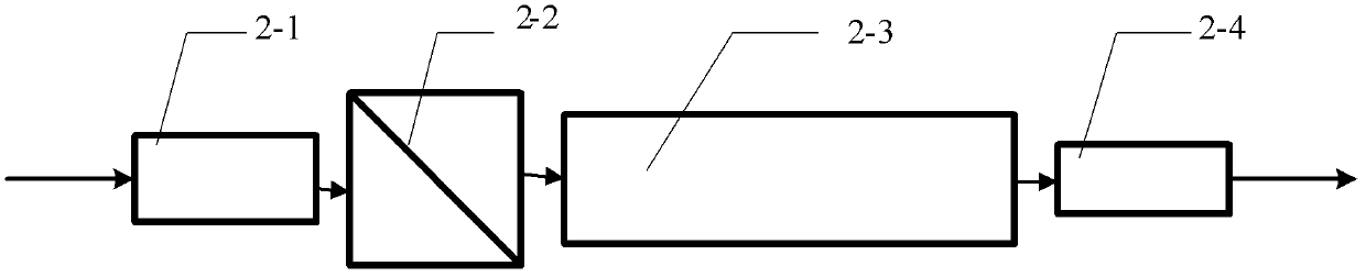
[0051] In the formula: is the Faraday rotation angle generated by the linearly polarized light passing through the optical sensor 2; is a constant proportional coefficient; V 1 Be the Verdet constant of the first magneto-optical glass 2-3 under normal temperature; i 1 is the current to be measured,

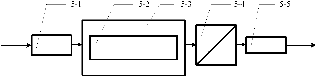
[0052] Step 2, the Faraday rotation angle produced by the linearly polarized light of the solenoid type self-inductance sensor 5 according to the Faraday magneto-optic effect With the current to be measured i 2 Expressed as:

[0053]

[0054] In the formula: is the Faraday rotation angle generated by the linearly polarized light throug...


PUM


Abstract

The invention relates to a temperature drift compensation optical current transformer and a current compensation method thereof, and aims to solve the problem of temperature drift influencing the measurement accuracy of the conventional optical current transformer. The temperature drift compensation optical current transformer further comprises a solenoid self-inductive sensor besides the conventional devices. An optical sensor is connected with the solenoid self-inductive sensor through a polarization maintaining fiber. The solenoid self-inductive sensor is connected with a signal processingunit through a multimode fiber. The signal processing unit is connected with the optical sensor through another multimode fiber. The temperature drift current compensation method comprises the following steps of: representing a Faraday angle of optical rotation generated by the linearly polarized light of the optical sensor by using current to be tested; representing a Faraday angle of optical rotation generated by the linearly polarized light of the solenoid self-inductive sensor by using offset current; deducing an output voltage expression according to an expression for the angle of optical rotation; and performing demonstration to realize the measurement of primary current. The temperature drift compensation optical current transformer and the current compensation method thereof are applied to the current measurement of a power system.

Description

technical field [0001] The invention belongs to the technical field of transformers, in particular to an optical current transformer for temperature drift compensation, and also relates to a current compensation method for the transformer. Background technique [0002] Current transformer is an indispensable basic equipment in power grid operation scheduling and production management. Its measurement accuracy and operation reliability are directly related to the safe, reliable and economical operation of the power system. In recent years, various forms of new electronic current transformers have been developed. Among them, optical current transformers based on the Faraday magneto-optic effect have excellent insulation performance, no transient magnetic saturation, large dynamic measurement range, wide frequency response, and anti-electromagnetic interference. With the advantages of strong capability, small size, light weight, and easy interface with digital equipment, it is ...

Claims


Application Information

Patent Timeline
IPC IPC(8): G01R15/24G01R19/32
Inventor 郭志忠于文斌张国庆路忠峰申岩李深旺王贵忠
Owner HARBIN INST OF TECH
Why Eureka
Try Eureka