
Optical-cement polarized beam splitting prism

A technology of polarizing beamsplitter prism and optical glue, which is applied in the field of optics and can solve the problems of expensive crystal materials, difficult processing, and high extinction ratio.

Inactive Publication Date: 2012-06-13
FUJIAN CASTECH CRYSTALS
View PDF5 Cites 6 Cited by
  • Summary
  • Abstract
  • Description
  • Claims
  • Application Information

AI Technical Summary

Problems solved by technology

Natural light is incident, and two beams of linearly polarized light with a high degree of polarization are emitted, Tp: Ts>1000:1, and the two beams of polarized light are perpendicular to each other, but in many system applications, a higher extinction ratio is required, and now Some glass polarizing prisms cannot meet the requirements, and the glued polarizing beamsplitter prism is almost impermeable to ultraviolet rays.
[0004] In addition, the existing Glan laser prism with high extinction ratio is made of birefringent crystal with high extinction ratio, but the crystal material is expensive, easy to cleavage and deliquescence, Not easy to process
[0005] Utility model patent ZL02215330.6 discloses a glass polarizing prism with a high extinction ratio, the oblique surfaces of two right-angle prisms are glued to a flat plate coated with polarized light-splitting film on both sides , using the gluing process, the ultraviolet and deep ultraviolet bands, the glue is almost opaque, and in other bands, the glue absorbs a lot; although the high extinction ratio of P light is guaranteed, the S polarized light is still a conventional extinction ratio

Method used


Image

  • Optical-cement polarized beam splitting prism
  • Optical-cement polarized beam splitting prism
  • Optical-cement polarized beam splitting prism

Examples


Embodiment Construction

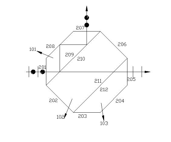
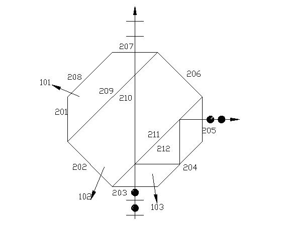
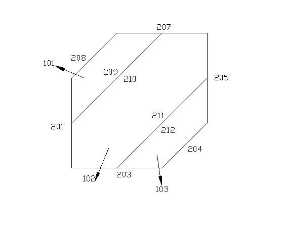
[0013] Such as figure 1 , select optical glass SF2, and process it into two identical base angles of 45° isosceles trapezoidal glass prisms 101 and 103 and a flat glass plate 102, with surfaces 201 to 212 polished, four waists 201, 207, 203 of the 45° isosceles trapezoidal prism , 205 are coated with anti-reflection film; the bottom surface 209, 212 is coated with polarized light-splitting film, and the glass block 210 is connected with the 209 faces of the 45o isosceles trapezoidal glass prism or deepened with optical glue; the glass block 211 is connected with the 212 of the 45o isosceles trapezoidal glass prism Surface light glue or deepen light glue connection.

[0014] The incident natural light is vertically incident from the waist surface 201 of the first 45° isosceles trapezoidal prism, and enters the first layer of polarized light splitting film 209, the P light is transmitted, and the S light is reflected; the P light passes through the flat glass plate 102 and enter...


PUM


Abstract

The invention discloses an optical-cement polarized beam splitting prism, which is characterized by comprising a pair of isosceles trapezoid glass prisms with 45-degree base angles and a glass plain film which are both made of general optical glass. The bottom surfaces of the isosceles trapezoid glass prisms with 45-degree base angles in pair are coated with the same polarized beam splitting film, and the glass plain film with two surfaces polished is arranged in the middle in optical cementing mode, thereby forming a sandwich structure. The structural order is: glass / polarized beam splitting film / glass / polarized beam splitting film / glass. The optical-cemented polarized beam splitting prism has a high damage threshold and a high extinction ratio, is low in cost, simple in structure, convenient to process and easy to manufacture in batches.

Description

technical field [0001] The invention relates to the field of optics, in particular to an optical glue polarization beam splitter prism in an optical element. Background technique [0002] Polarizing prism is a kind of device that is often used in the polarization optical path. It mainly plays the role of polarization splitting. It is widely used in consumer industries such as laser systems, optical communication devices, optical test and measuring instruments, and display instruments. [0003] The structure of the existing glass polarizing beam-splitting prism is as follows: it is composed of a pair of right-angled prisms, the slope of one of the right-angled prisms is coated with a polarization beam-splitting film, and the slope of the other right-angled prism is a polished surface. As a result, the four right-angle surfaces are coated with anti-reflection coatings to reduce the reflection loss when light passes through the prism. Natural light is incident, and two beams o...

Claims


Application Information

Patent Timeline
IPC IPC(8): G02B5/04G02B5/30G02B1/11
Inventor 朱一村吴季吴少凡
Owner FUJIAN CASTECH CRYSTALS
Learn More