
Smart grid hub

A technology of smart grid and hub station, applied in electrical components, circuit devices, information technology support systems, etc., can solve the problems of development and operation management that are not suitable for scientific and technological progress, increase construction period, and low work efficiency, and achieve easy expansion. , cost saving, low operating power

Inactive Publication Date: 2014-10-22
SHANGHAI LANYIN INDAL
View PDF4 Cites 0 Cited by
  • Summary
  • Abstract
  • Description
  • Claims
  • Application Information

AI Technical Summary

Problems solved by technology

[0003] However, their data collection and control methods are all done manually. Every time data is collected, someone needs to go to the site to operate it. This manual management method is no longer suitable for the development of scientific and technological progress and the needs of operation management.
In the general cable branch box or ring network cabinet, the original power supply trunk cable is cut off and then connected to the busbar of the branch box, and then a similar cable is connected from the busbar to the original place to connect with the cut trunk cable. Regardless of the thickness of the new load, it must be the same as the original trunk cable to ensure the normal operation of the original load. This is not economical, wastes materials and is not environmentally friendly. It also increases the construction period, heavy workload, and low work efficiency.

Method used


Image

  • Smart grid hub
  • Smart grid hub
  • Smart grid hub

Examples


Embodiment Construction

[0033] Embodiments of the present invention will be described in detail below in conjunction with the accompanying drawings.

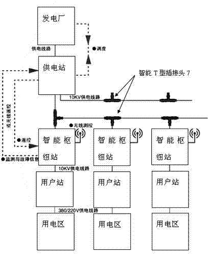
[0034] Such as figure 1 As shown, a distributed power supply system structure adopts T-shaped joints in the structure of the power supply system. It includes a power plant, a power supply station connected with the power plant through cables, and several trunk cables output by the power supply station, and several T-shaped connectors are arranged on each trunk cable. Through the T-shaped joint, several branch cables are branched from each main circuit cable, and each branch cable circuit is connected to the input terminal of a smart grid hub station disclosed in the present invention, and the output terminal of the smart grid hub station is connected to The user station, the output end of the user station is connected to the user area through a cable.

[0035] The power produced by the power plant is transmitted to the power supply station. The power...


PUM


Abstract

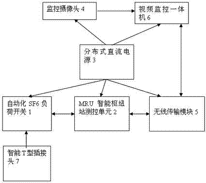
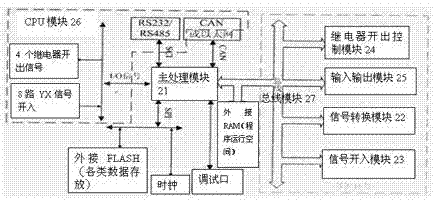
The invention discloses a smart power grid junction station, which comprises a mobile radio unit (MRU) smart junction station measurement and control unit, an automatic sulfur hexafluoride (SF6) load switch, a smart T type plug connector, a wireless transmission module, a video monitoring all-in-one machine, a monitoring camera and a distributed direct current power supply, wherein the automatic SF6 load switch is in circuit connection with the MRU smart junction station measurement and control unit; the smart T type plug connector is connected with the automatic SF6 load switch; the wireless transmission module is in circuit connection with the MRU smart junction station measurement and control unit; the video monitoring all-in-one machine is in circuit connection with the wireless transmission module; and the output end of the monitoring camera is in circuit connection with the video monitoring all-in-one machine. The automatic SF6 load switch monitored by the MRU smart junction station measurement and control unit is adopted, a control instruction is transmitted to the automatic SF6 load switch to turn off or turn on branch cables, and influence on the running of a primary grid in regional overhauling is avoided; cost is saved, switch positions are saved for power transformer substations, the construction of the power transformer substations is reduced, additional nodes are conveniently arranged for the product, and the product is high in extensibility; and the MRU smart junction station measurement and control unit can be replaced by a feeder terminal unit or a distribution terminal unit.

Description

technical field [0001] The invention relates to a system for on-line load monitoring, diagnosis and wireless control of a power distribution branch cable connected through an intelligent T-shaped plug-in cable, in particular to an intelligent grid hub station. Background technique [0002] With the continuous development of the economy and the increasing impact of electric energy on people's lives, especially for urban areas with high load density, the reliability of power supply is particularly important. Replacing overhead lines with existing cables can effectively improve the reliability of power supply and ensure The continuity of power supply minimizes the impact of power distribution equipment failures and maintenance blackouts. Ring network cabinets and cable branch boxes are very important key equipment in the ring network operation mode. [0003] However, their data collection and control methods are all done manually. Every time data is collected, someone needs to ...

Claims


Application Information

Patent Timeline
Patent Type & Authority Patents(China)
IPC IPC(8): H02J13/00
CPCY04S20/18Y02B90/228Y02B90/20
Inventor 朱国平
Owner SHANGHAI LANYIN INDAL
Learn More