Work piece installing and clamping device in ion beam polishing process and method thereof

A clamping device and ion beam technology, which is applied in the direction of grinding/polishing equipment, electrical components, manufacturing tools, etc., can solve the problems of curvature radius, damaged layer, eccentricity, roughness, and harsh surface PV value, etc., to achieve increased Large effective processing area, simple structure, and the effect of preventing structural damage

Active Publication Date: 2012-06-20
INST OF OPTICS & ELECTRONICS - CHINESE ACAD OF SCI
View PDF7 Cites 24 Cited by
  • Summary
  • Abstract
  • Description
  • Claims
  • Application Information

AI Technical Summary

Problems solved by technology

The quality requirements of lithography objective optical components are an order of magnitude higher than other high-precision optical components. For example, the radius of curvature is less than or equal to 1 μm, the surface error is less than or equal to λ/20~λ/100, and the rms root mean square value is less than or equal to It is

Method used


Image

  • Work piece installing and clamping device in ion beam polishing process and method thereof
  • Work piece installing and clamping device in ion beam polishing process and method thereof
  • Work piece installing and clamping device in ion beam polishing process and method thereof

Examples


Embodiment 1

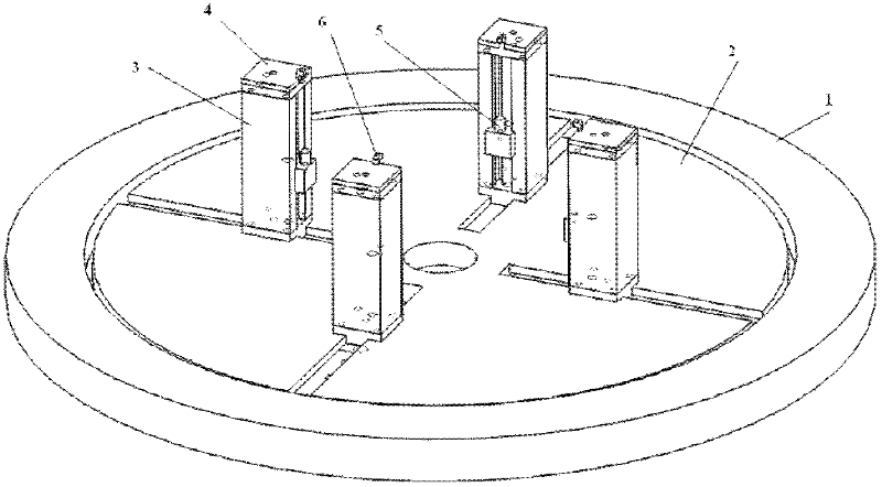
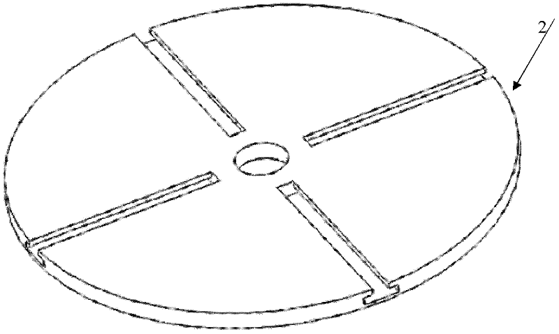
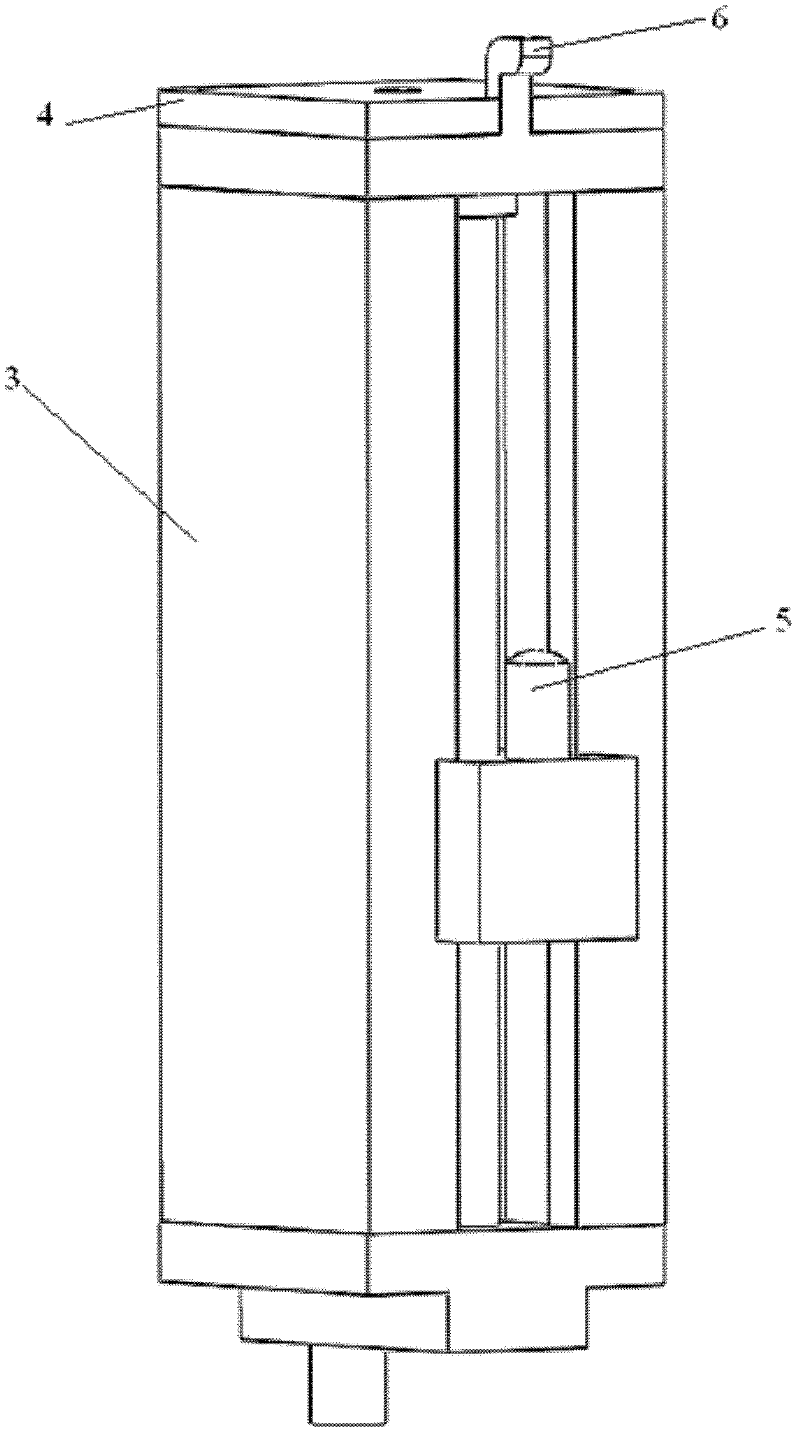
[0029] Example 1: Combining figure 1 The embodiment of the workpiece clamping device in the ion beam polishing process of the present invention includes a clamping main platform 1, a four-slot rotary table 2, a sliding fixed column 3, a ceramic cap piece 4, a lifting bracket structure 5 and a hook 6. The four-slot turntable 2 has four guide rail chutes orthogonally distributed in four directions on the upper end surface. The four-slot turntable 2 can be made of stainless steel, and the lower end surface is installed on the main card-loading platform 1 through a clamping structure and a ball connection, which can realize Free spins. Lifting bracket structure 5 and hook 6 are arranged on sliding fixed column 3, and hook 6 is installed on the upper end surface of sliding fixed column 3 by bolt, and the screw rod of lifting bracket structure 5 is installed in sliding fixed column 3 inside, and cylindrical support is installed on the screw rod, through The upper end surface of the...

Embodiment 2

[0032] Embodiment 2: Combination figure 1 Describe this embodiment, this embodiment is realized through the following steps:

[0033] Step S1: Determine a workpiece to be clamped and processed. The workpiece is assumed to be circular, with a diameter of Φ200mm and a thickness of 40mm. The upper surface is a convex spherical surface, and the lower surface is a concave spherical surface. According to the shape and size of the workpiece to be clamped, adjust the position of the movable fixed column 3 on the four-slot rotary table 2, so that the inner end surface of the sliding fixed column 3 is about 100mm away from the center of the four-slot rotary table 2, and fasten three of them. A sliding fixed column 3, the other remains loose and slidable;

[0034] Step S2: Adjust the distance between the lifting bracket structure 5 on the sliding fixing column 3 and the hook 6 to about 41 mm, move the loose sliding fixing column 3, and fix the workpiece to be loaded on the lifting brack...


PUM


Abstract

The invention relates to a work piece installing and clamping device in an ion beam polishing process and a method thereof. The work piece installing and clamping device comprises a four-groove rotary platform which is fixed on a clamping main platform, wherein four grooves are symmetrically distributed on the four-groove rotary platform in orthogonal mode, four slide fixing columns are respectively arranged on the four grooves of the four-groove rotary platform, the slide fixing columns can be fixed or loosened by screwing fixing bolts on the slide fixing columns, ceramic cap pieces are fixed on the upper surfaces of the slide fixing columns, a hanging hook is respectively positioned on the lateral faces of the slide fixing columns, and a lifting support structure is respectively installed and clamped on the slide fixing column on the lower side of the hanging hook. The work piece installing and clamping method is that the four-groove rotary platform is fixed on the clamping main platform, work pieces can be installed and clamped on the four-groove rotary platform structure through the slide fixing columns, and the distance between the work piece and the slide fixing columns can be measured by utilizing a dial gauge to rorate the four-groove rotary platform, the positions of the slide fixing columns can be moved to adjust the same distance to guarantee center uniformity of the centers of the work pieces and the installing and clamping main platform, and accordingly accurate installing and clamping of the positions of the work pieces are achieved.

Description

technical field [0001] The invention belongs to the technical field of optical manufacturing of photolithography systems, and relates to a workpiece clamping method and device in the ion beam polishing process. Background technique [0002] The key equipment for microelectronics is an important support for microelectronics technology. The lithography objective lens is the key core part of the distributed and repeated projection lithography of special equipment for microelectronics. direct relation. The quality requirements of lithography objective optical components are an order of magnitude higher than other high-precision optical components. For example, the radius of curvature is less than or equal to 1 μm, the surface error is less than or equal to λ / 20~λ / 100, and the rms root mean square value is less than or equal to It is equal to λ / 100~λ / 300, etc., and puts forward extremely strict requirements on the accuracy of the outer diameter, center thickness, radius of curva...

Claims


Application Information

Patent Timeline
IPC IPC(8): B24B13/005H01L21/67
Inventor 施春燕钟显云万勇建范斌伍凡张亮
Owner INST OF OPTICS & ELECTRONICS - CHINESE ACAD OF SCI
Why Eureka
Try Eureka