Recovery method of ammonia from vent gas during ammonia synthesis

A technology for venting and ammonia recovery, applied in the preparation/separation of ammonia, etc., can solve the problems of no vent, loss of refining gas, and increased load of ammonia scrubber, etc., to achieve easy equipment installation, small equipment diameter, and no space occupation. Effect

Inactive Publication Date: 2013-06-05
刘军
View PDF3 Cites 0 Cited by
  • Summary
  • Abstract
  • Description
  • Claims
  • Application Information

AI Technical Summary

Problems solved by technology

[0007] 1. The position of the venting port is after the third ammonia separator, and the gas supply position is before the third ammonia separator, that is, the venting process after the gas supply. Although the ammonia content in the vented air is low, there is refined gas that has just been replenished in the vented air , the refined gas is also released together, the refined gas is lost, the consumption of refined gas is high, the amount of air released is large, and the cost of synthetic ammonia is increased;
[0008] 2. The position of the venting port is before the inlet of the ammonia cooler, and before the position of the refining gas replenishment port, that is, the venting process before the gas replenishment. Although there is no refined gas in the vented air and the amount of vented air is small, the ammonia content in the vented air is high, which aggravates the problem. The load of the ammonia washing tower increases the ammonia content at the outlet of the ammonia washing tower, and more ammonia water is recovered;
[0009] 3. At present, whether the position of the vent port is after the third ammonia separator, the position of the gas supply is before the third ammonia separator, after the venting process, or the position of the vent port is before the inlet of the ammonia cooler, and the gas supply port of the refining gas The venting process before replenishing the air before the position is that the vented air is not processed after the vented air exits the vent port, and the vented air exiting the vent port goes directly to the ammonia washing tower for hydrogen extraction. There is no special purpose for separation and recovery when venting There is an ammonia separator with liquid ammonia in the air, so there is no vent port for the best of both worlds, so the current ammonia synthesis process can only be vented at one of the two vent ports that have obvious deficiencies;
[0010] 4. Some factories release the air with high ammonia content before the inlet of the circulating air of the ammonia cooler to the newly added ammonia cooler outside the ammonia synthesis process, and use the cooling capacity of the ammonia cooler to evaporate the liquid ammonia into gaseous ammonia Cool the vented air, condense the gaseous ammonia in the vented air into liquid ammonia, and then separate the liquid ammonia from the vented air to recover ammonia and synthesize the ammonia in the vented air. Three high-pressure equipment, namely, cold exchange, ammonia cooler and ammonia separator, should be added. , but also to add supporting high-pressure regulating valves, high-pressure liquid level gauges and medium-pressure regulating valves, medium-pressure liquid level gauges, and supporting temperature measuring instruments. The process is complicated, there are many high-pressure equipment, and the investment in high-pressure equipment is high. more, and increase the workload of the operator

Method used


Image

  • Recovery method of ammonia from vent gas during ammonia synthesis
  • Recovery method of ammonia from vent gas during ammonia synthesis
  • Recovery method of ammonia from vent gas during ammonia synthesis

Examples


Embodiment Construction

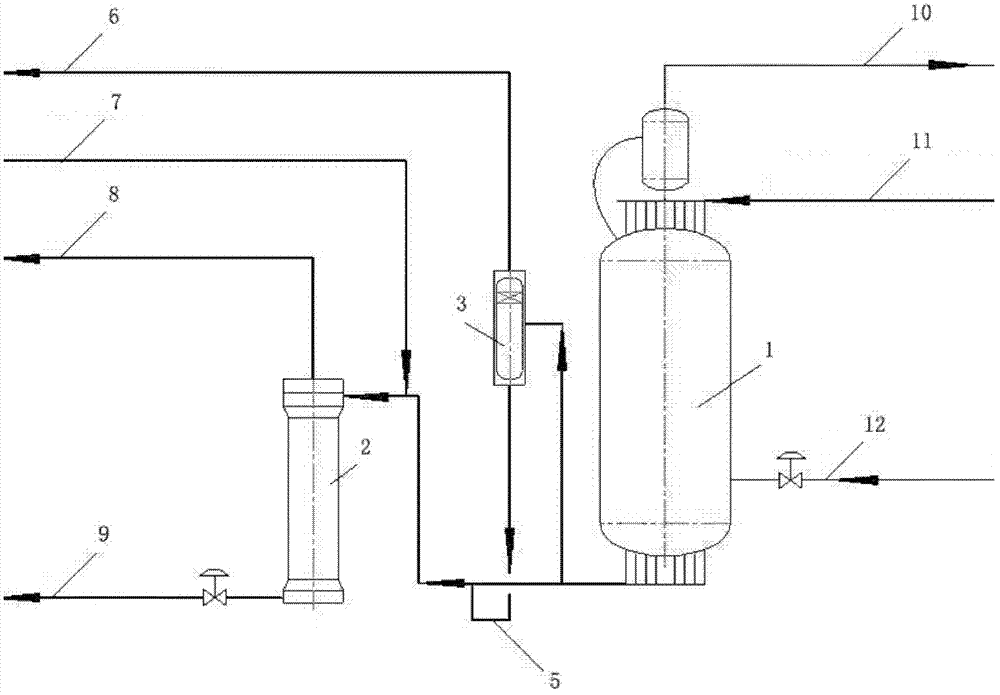
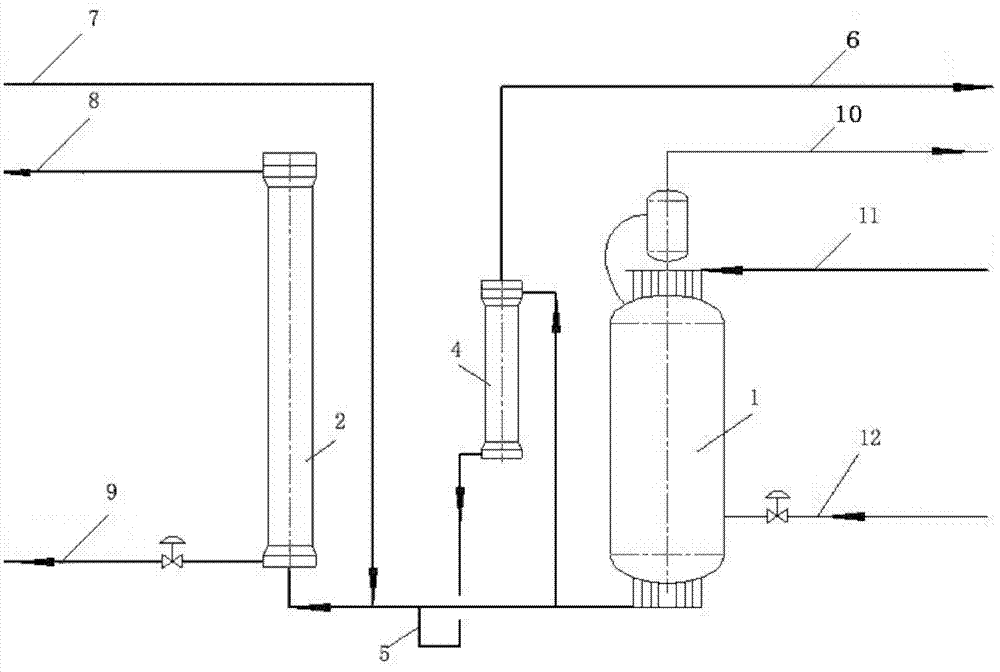
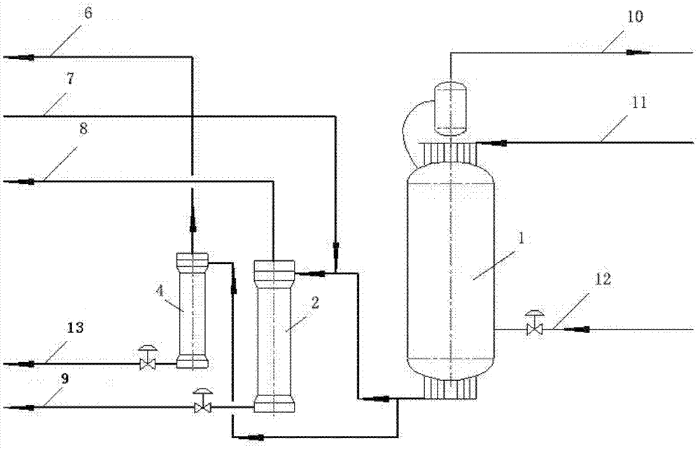
[0038] see figure 1 , 2 , 3,1-Ammonia cooler, 2-The third ammonia separator, 3-Small ammonia separator, 4-Old ammonia separator, 5-U-shaped liquid-sealed pipe, 6-Release the air to extract the ammonia scrubber, 7- Refining gas replenishment gas inlet pipe, 8- Circulating gas return cooling delivery inlet, 9- Third ammonia separator liquid ammonia removal ammonia main pipe, 10- Gas ammonia return freezing process, 11- Ammonia cooler inlet circulation gas pipe, 12 -Liquid ammonia comes from the freezing process, 13-Liquid ammonia from the old ammonia separator goes to the ammonia discharge main pipe.

[0039] see figure 1 , move the position of the vent port from the inlet pipe of the ammonia cooler 1 to the outlet of the ammonia cooler 1 and the inlet of the third ammonia separator 2, where the circulating gas is cooled by the ammonia cooler 1, The temperature has dropped to -5 ~ 0 ℃, most of the ammonia in the circulating gas is condensed into liquid ammonia, and the ammoni...


PUM


Abstract

The invention relates to a recovery method of ammonia from vent gas during ammonia synthesis in an ammonia synthesis plant. The method comprises the steps of: moving a vent position to a circulating gas pipeline before the outlet of an ammonia cooler and a third ammonia separator, and moving a refinery gas supplementing port to a circulating gas pipeline after the vent and before the third ammonia separator; additionally installing a small ammonia separator or installing a used ammonia separator for separating and recovering liquid ammonia in the vent gas cooled by the ammonia cooler; connecting a vent gas pipe led from the vent with the gas inlet of the small ammonia separator or used ammonia separator, and connecting the vent gas outlet of the small ammonia separator or used ammonia separator to a hydrogen-extracting ammonia washing tower; and automatically returning liquid ammonia separated and recovered by the small ammonia separator or used ammonia separator to the circulating gas pipeline after the outlet of the ammonia cooler and the vent for recovering, and then entering liquid ammonia into the third ammonia separator together with circulating gas to separate ammonia. According to the method provided by the invention, only one high-pressure device is increased, and the complement investment is not needed or the complement investment is lower.

Description

technical field [0001] The invention relates to a method for recovering ammonia from air released from ammonia synthesis in an ammonia synthesis plant. Background technique [0002] In the prior art, there are two vent positions in the ammonia synthesis process of each ammonia synthesis plant, one is after the third ammonia separator, and the gas replenishment position is before the third ammonia separator, which belongs to the vent after gas replenishment. Venting here, the synthetic cycle gas has passed through the ammonia cooler and the third ammonia separator, the ammonia content in the vented air is the lowest, and the ammonia content is generally about 2.5% (volume). The ammonia water generated in the ammonia washing tower is less. However, there is the refined gas that has just been supplemented in the vented air, and the refined gas is also released together, which loses the refined gas that contains about 74% (volume) hydrogen and is refined through multiple proces...

Claims


Application Information

Patent Timeline
Patent Type & Authority Patents(China)
IPC IPC(8): C01C1/12
Inventor 刘军
Owner 刘军
Why Eureka
Try Eureka