Spent catalyst distributor and spent catalyst distribution method for fluid catalytic cracking device

A technology of fluidized catalytic cracking and standby catalyst, which is applied in the direction of catalytic cracking, cracking, petroleum industry, etc., and achieves the effect of small influence, small gas flow rate and good distribution uniformity

Inactive Publication Date: 2012-06-20
CHINA UNIV OF PETROLEUM (BEIJING)
View PDF7 Cites 3 Cited by
  • Summary
  • Abstract
  • Description
  • Claims
  • Application Information

AI Technical Summary

Problems solved by technology

[0008] The main purpose of the present invention is to provide a new type of spent catalyst distributor aiming at the shortcomings of the existing catalytic cracking spent catalyst distributor technology, so that the spent catalyst can be distributed more evenly

Method used


Image

  • Spent catalyst distributor and spent catalyst distribution method for fluid catalytic cracking device
  • Spent catalyst distributor and spent catalyst distribution method for fluid catalytic cracking device
  • Spent catalyst distributor and spent catalyst distribution method for fluid catalytic cracking device

Examples


Embodiment 1

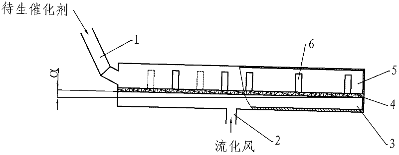
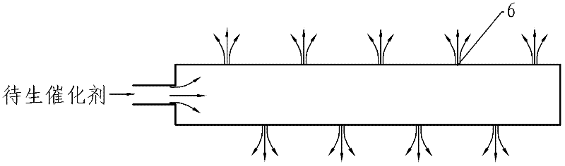
[0042] This embodiment provides a spent catalyst distributor for a fluid catalytic cracking unit, and the distributor includes a plurality of spent catalyst distribution tanks. See Figure 1A with Figure 1B As shown, the structure and distribution principle of the spent catalyst distributor of the present invention are illustrated, and the structure shown in the figure represents a catalyst distribution tank of the spent catalyst distributor in an actual industrial device. in, Figure 1A is the front view, Figure 1B For top view. As shown in the figure, the catalyst distribution tank of the distributor has a double-layer tank structure with an upper tank body and a lower tank body that are basically arranged in parallel. The raw catalyst conveying standpipe 1 is connected, and a plurality of catalyst distribution holes 6 are opened on both sides of the upper tank body; the lower tank body is a fluidizing wind buffer chamber 3, and a fluidizing wind inlet is set to connect ...

Embodiment 2

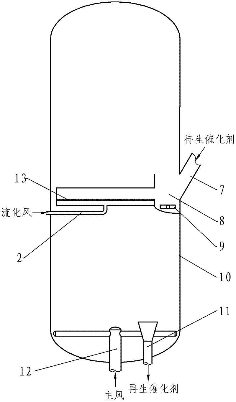
[0045] figure 2 with image 3 It shows an overall structural arrangement of the standby catalyst distributor of the present invention in a parallel catalytic cracking unit. In this embodiment, the standby catalyst distributor is provided with a standby catalyst pre-distribution chamber 8, and multiple standby catalyst distributors The waiting catalyst distribution cavity of the distribution tank 13 is all communicated with the pre-distribution cavity 8, as image 3 shown. Each waiting catalyst distribution tank 13 adopts Figure 1A with Figure 1B In the structure shown, one or more fluidizing air pipes 2 are connected to the fluidizing wind buffer chamber 3 at the bottom. The number and length of the spent catalyst distribution grooves 13 can be determined according to the size of the regenerator 10 to be used, and should cover all cross-sectional areas as much as possible to achieve a more uniform distribution of the spent catalyst. The height of the distributing tank 1...

Embodiment 3

[0049] Figure 5 with Image 6 An overall structural arrangement of the spent catalyst distributor of the present invention in a coaxial catalytic cracking unit is given. In this embodiment, the pre-distribution chamber 14 of the distributor is arranged around the standby standpipe 7 in the regenerator, and the horizontal arrangement of multiple standby agent distribution tanks 13 is as follows Image 6 As shown, with the pre-distribution chamber 14 as the center, it is distributed radially to the surroundings to basically cover the entire cross-section of the regenerator. Figure 1A with Figure 1B In the structure shown, one or more fluidizing air pipes 2 are connected to the fluidizing wind buffer chamber 3 at the bottom. Such as Figure 5 As shown, a plug valve 17 and a plug valve sleeve 18 are arranged at the outlet end of the spent agent of the standpipe 17 in the regenerator.

[0050] The spent catalyst from the standby riser 7 first enters the plug valve sleeve 18, t...


PUM


Abstract

The invention provides a spent catalyst distributor and a spent catalyst distribution method for a fluid catalytic cracking device. The spent catalyst distributor comprises at least one spent catalyst distribution trough provided with an upper structure and a lower structure parallel to each other, the upper trough body and the lower trough body are separated by a gas distribution plate, the upper trough body is a spent catalyst distribution cavity communicated with a spent catalyst delivery standpipe, two sides of the upper trough body are provided with a plurality of catalyst distribution holes, the lower trough body is a fluidizing air buffer cavity provided with a fluidizing air inlet, the gas distribution plate is provided with gas distribution holes by which the spent catalyst distribution cavity is communicated with the fluidizing air buffer cavity, gas flowing into the fluidizing air buffer cavity evenly flows into the spent catalyst distribution cavity through the gas distribution holes, and a layer of catalyst solid particles in the distribution cavity are fluidized and flow out of the distribution holes on two sides of the upper trough body. The spent catalyst distributor is uniform in catalyst distribution, required gas flow is low, wear of equipment and particles is low, and impact on resistance and stability of a spent catalyst particle delivery pipeline is low.

Description

technical field [0001] The invention belongs to the field of petroleum processing, and in particular relates to a spent catalyst distributor used in a fluidized catalytic cracking unit in the petrochemical industry and an application method thereof in a regenerator of a fluidized catalytic cracking unit. Background technique [0002] The fluid catalytic cracking process is one of the core light oil production processes in modern oil refineries. It uses molecular sieve catalysts to crack low-value heavy raw materials (wax oil and residual oil) into high-value light oil products, such as Gasoline, diesel and liquefied petroleum gas, etc. In my country, the core position of the fluid catalytic cracking process is more prominent, leading the production of 70% to 80% of commercial gasoline, about 30% of commercial diesel oil and about 30% of propylene. Therefore, the development of new technologies to improve the distribution of FCC products or improve the reliability of FCC uni...

Claims


Application Information

Patent Timeline
IPC IPC(8): C10G11/18
Inventor 张永民禹淞元卢春喜
Owner CHINA UNIV OF PETROLEUM (BEIJING)
Why Eureka
Try Eureka