Hydraulic driving system of hydraulic-driven ship lift

A technology of hydraulic drive and ship lift, which is applied in the vertical lifting of ship machinery, ship lifting devices, buildings, etc., can solve the problems of complex control, system balance damage, high operation and maintenance costs, and achieve high control accuracy and balanced tension , the effect of smooth stop

Active Publication Date: 2012-06-20
XIAN AEROSPACE AUTOMATION
View PDF9 Cites 10 Cited by
  • Summary
  • Abstract
  • Description
  • Claims
  • Application Information

AI Technical Summary

Problems solved by technology

[0003] 1. The torque balance and speed of multiple motors are required to be balanced, so the control is complicated;
[0004] 2. Water leakage in the ship’s compartment cannot be tolerated. Once the ship’s compartment leaks, the balance of the system will be destroyed and serious safety accidents will occur. Therefore, the sealing requirements of the ship’s compartment are strict
[0005] 3. The operation and maintenance requirements of electric drive are strict, which makes the operation and maintenance cost higher
[0006] The hydraulically driven ship lift can overcome the above-mentioned shortcoming of electric drive. Chinese patent ZL99116476.8 discloses a hydraulically driven ship lift (it is called hydraulic floating torque balance weight lifting mechanism), but it only Provides the basic ideas for the realization of the hydraulic drive system, but its system composition is still far from perfect and cannot reach the level of practical application

Method used


Image

  • Hydraulic driving system of hydraulic-driven ship lift
  • Hydraulic driving system of hydraulic-driven ship lift
  • Hydraulic driving system of hydraulic-driven ship lift

Examples


Embodiment Construction

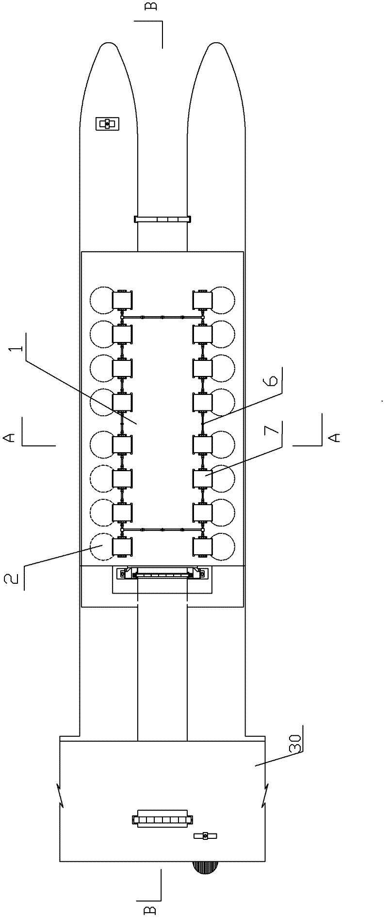
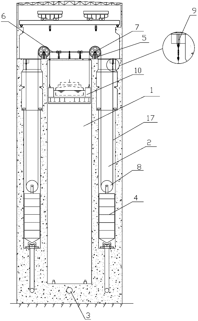
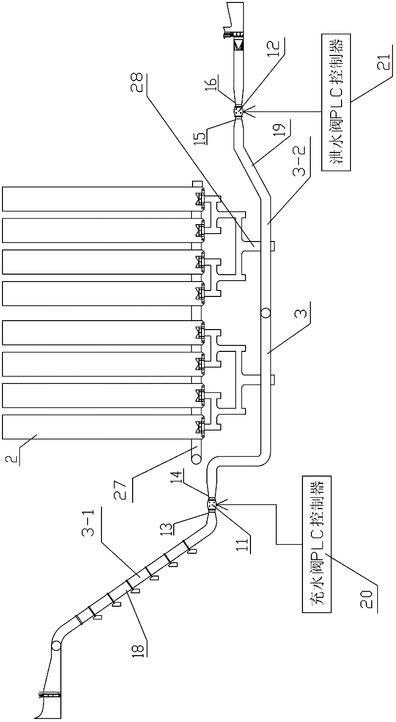
[0034] see Figure 1~3 , it has a ship-holding box vertical lifting operation channel 1, and the ship-holding box vertical lifting operation channel 1 is vertically arranged with the dam 30 (such as figure 1 As shown), two rows of axisymmetric buoy shafts 2 are arranged on both sides of the vertical lifting operation channel 1 of the ship-bearing box. In this example, sixteen buoy shafts are arranged in total, and one row is provided with eight. Each of the buoy shafts The lower end of 2 communicates with a main pipeline 3 through an equal inertia water delivery piping system. The equal inertia water delivery piping system is to ensure that the water levels in the sixteen shafts rise or fall at the same time when filling and discharging water. The water delivery piping system is It is set up in this way: first, the bottoms of the buoy shafts 2 are horizontally connected with the pipeline 27, and then according to the principle of dividing into two and dividing into four, the m...


PUM


Abstract

The invention relates to a hydraulic driving system of a hydraulic-driven ship lift. The hydraulic driving system is provided with a ship lift chamber vertical lifting operation passage. Two axisymmetric rows of floating camel shafts are arranged on the two sides of the passage. The lower end of each floating camel shaft is communicated with a main pipe through an equal-inertia conveyance system. A filling valve and a drain valve are respectively arranged at the upstream and the downstream of the main pipe. A counter weight floating camel is arranged in each floating camel shaft. A rectangular synchronous driving shaft is arranged at the top of the ship lift chamber operation passage. A steel wire rope hoisting mechanism is arranged among each counter weight floating camel, the rectangular synchronous driving shaft and the ship lift chamber. The filing valve and the drain valve are intelligent control valves which are the most advanced at preset. The filled flow and the drained flow of the filling valve and the drain valve are respectively controlled by a filling valve programmable logic controller (PLC) and a drain valve PLC. A closed-loop control system for detecting and controlling the filled flow and the drained flow is formed. At the same time, each of the filling valve and the drain valve adopts a one-main two-auxiliary structure to enable the control of the filled flow and the drained flow and the stopping position of the ship lift to be more precise.

Description

technical field [0001] The invention relates to a driving system of a ship lift, in particular, it is a hydraulic driving system of a hydraulically driven ship lift. Background technique [0002] At present, there are two types of large-scale ship lifts at home and abroad, one is an electric-driven ship lift, and the other is a hydraulic-driven ship lift. The technical core of the electric-driven ship lift is to use multiple motors to synchronously drive a rectangular shaft to rotate, thereby driving multiple steel wire winches to rotate, and to realize the function of synchronously hoisting and lifting or lowering the ship's container. For specific technical content, please refer to China Patent ZL00113933.9. The deficiencies that this type of ship lift exists are as follows: [0003] 1. The torque balance and speed of multiple motors are required to be balanced, so the control is complicated; [0004] 2. Water leakage in the ship's compartment cannot be tolerated. Once ...

Claims


Application Information

Patent Timeline
Patent Type & Authority Applications(China)
IPC IPC(8): E02C5/02
Inventor 易春辉石晓俊刘锦
Owner XIAN AEROSPACE AUTOMATION
Why Eureka
Try Eureka