Optical condensation solar heat collector used at low temperature

A technology of concentrating solar energy and heat collectors, applied in the field of solar energy utilization, can solve the problems of reduced power generation efficiency, inability to use non-vacuum heat collector tubes, large heat loss, etc., to achieve the effect of convenient application and high efficiency

Inactive Publication Date: 2012-06-20
李德杰
View PDF7 Cites 6 Cited by
  • Summary
  • Abstract
  • Description
  • Claims
  • Application Information

AI Technical Summary

Problems solved by technology

Since the working temperature is as high as above 400°C, non-vacuum heat collecting tubes cannot be use

Method used


Image

  • Optical condensation solar heat collector used at low temperature
  • Optical condensation solar heat collector used at low temperature
  • Optical condensation solar heat collector used at low temperature

Examples


Embodiment 1

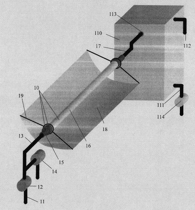
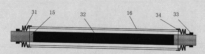
[0024] Concentrating solar collectors for low temperature with non-circulating structure, using a 2-meter-diameter concentrator, a stainless steel collector tube inner tube with an outer diameter of 70 mm, coated with black chrome sunlight absorbing layer; the outer tube of the collector tube is made of borosilicate glass, with a diameter of 100 mm. The effective length of the heat collecting tube is 4 meters, and the volume of the water tank is 500 liters. In the 40-50 north latitude area, the system can provide 250 liters of warm water at 60 degrees when the winter solstice is sunny.

Embodiment 2

[0026] Similar to Example 1, but with a cyclic structure.

Embodiment 3

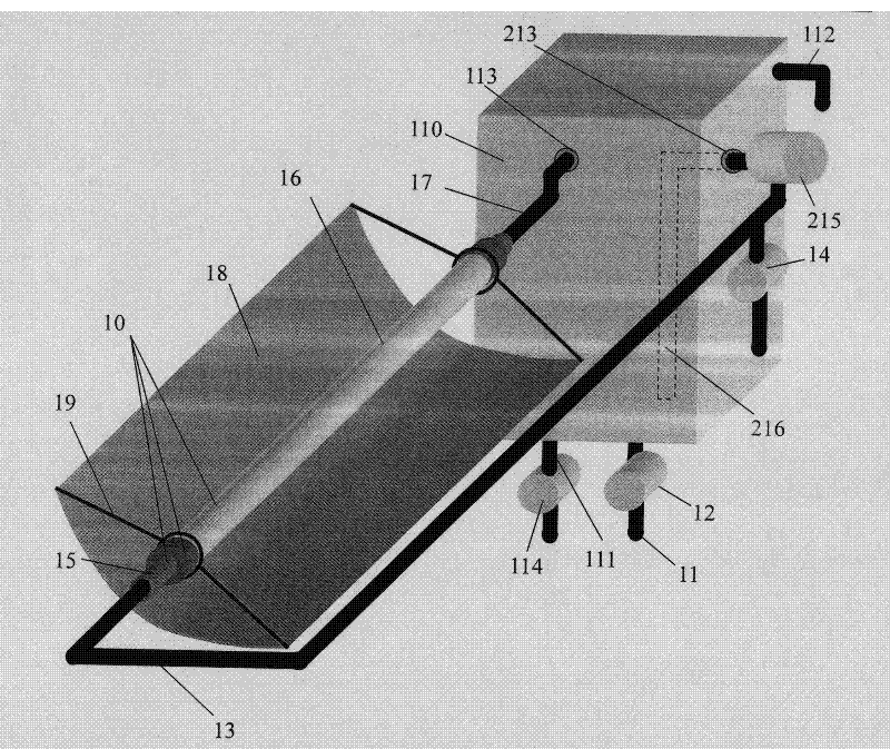
[0028] Concentrating solar collector for low temperature with non-circulating structure, using a 2-meter-caliber concentrating mirror, and a stainless steel collector tube with an outer diameter of 70 mm, which is coated with Mo-Al 2 o 3The sunlight absorbing layer; the outer tube of the heat collecting tube is made of borosilicate glass with a diameter of 100mm. The effective length of a single tube of the heat collecting tube is 4 meters, and two tubes are connected in series to form two heat collectors with a length of 8 meters each, and the volume of the common water tank is 2000 liters. The sunlight intensity detector, the outdoor temperature sensor, the water level sensor in the water tank, the water tank temperature sensor etc. share a set, the water temperature sensor on the water outlet connecting pipe is set separately, and the water injection valve is controlled separately. In the area of ​​40-50 north latitude, the system can provide 1200 liters of 60-degree warm ...


PUM


Abstract

The invention discloses an optical condensation solar heat collector used at low temperature and belongs to the field of solar energy utilization, wherein the optical condensation solar heat collector comprises a non-vacuum heat collection pipe, an optical condenser, a water tank and inlet and outlet water pipes. The used heat collection pipe is of a non-vacuum type; the inner pipe of the heat collection pipe is a metal pipe, and the surface of the inner pipe is higher in sunlight absorption ratio and lower in infrared emission ratio, and the outer pipe of the heat collection pipe is a glass pipe or a transparent organic pipe; the relative position of the inner pipe and the outer pipe is fixed by a support member and is subjected to dustproof and rainproof seal instead of vacuum seal, and atmosphere instead of vacuum is filled between the inner pipe and the outer pipe; an acyclic structure is adopted for the system, i.e., cold water passes through the inner pipe of the heat collection pipe in one step and is heated up to the final temperature; and the cyclic structure can be adopted to be used in areas in short of water pressure often, and water is repeatedly circulated between the inner pipe and outer pipe of the heat collection pipe through the water pump so as to reach the final temperature. According to the invention, the optothermal conversion efficiency is high, the comprehensive cost is low, the operation is reliable, and the optical condensation solar heat collector used at low temperature is especially suitable for concentrated hot water supply for high-level folk houses, and can be produced on a large scale.

Description

Technical field: [0001] The invention relates to a concentrated solar heat collector for low temperature and belongs to the technical field of solar energy utilization. Background technique: [0002] Solar heat collectors have been widely used in residential hot water supply, but there are many problems, including water leakage in the in-line structure and freezing and cracking of heat collecting pipes in winter. Regardless of the in-line or heat pipe structure, the actual light-to-heat conversion efficiency achieved is generally lower than 40%. For such a low thermal efficiency, in common high-rise residential buildings, even if the roof is fully utilized, it can only meet the needs of a small number of families. Currently, only residents close to the top floor can use solar water heaters, and the installation is messy, which affects the appearance of the city. Although balcony-type heat collectors are also being developed, there are more problems and it is difficult to p...

Claims


Application Information

Patent Timeline
IPC IPC(8): F24J2/24F24J2/10F24J2/38F24J2/46F24J2/48F24J2/40F24S10/70F24S23/70
CPCY02E10/47Y02E10/44
Inventor 李德杰
Owner 李德杰
Why Eureka
Try Eureka