
Inflammable gas detecting instrument and desulphurization method thereof

A gas detector and circuit technology, which is applied in the field of combustible gas detectors and sulfur removal, can solve the problems of catalytic sensors such as large influence, poisoning, and reduced catalytic activity, and achieve reliable and accurate detection, accurate measurement results, and improved sensitivity.

Active Publication Date: 2012-06-20
HENAN HANWEI ELECTRONICS
View PDF4 Cites 4 Cited by
  • Summary
  • Abstract
  • Description
  • Claims
  • Application Information

AI Technical Summary

Problems solved by technology

[0004] However, in the process of use, it is found that the catalytic combustion gas sensor also has defects, that is, the catalyst of the sensor, like other catalysts, has poisoning phenomenon and is easily affected by sulfide, halogen compounds, Si, Sb, Pb and other substances. The activity will gradually decrease, resulting in a decrease in the sensitivity of the sensor, also known as sensor poisoning
[0005] The hydrogen sulfide gas in the industrial and mining environment has the greatest impact on the catalytic sensor. It will cause the catalyst in the catalytic sensor to lose its activity in a short time, thereby reducing the sensitivity of the sensor; the poisoning of the catalytic sensor by hydrogen sulfide gas is mainly caused by two reasons. The first is that hydrogen sulfide is more easily adsorbed to the active site of the catalyst than methane gas, which reduces the number of effective active centers of the catalyst; the second is that hydrogen sulfide gas reacts with metal oxide catalysts to form platinum, palladium and other noble metal sulfides , thereby deactivating the catalyst

Method used


Image

  • Inflammable gas detecting instrument and desulphurization method thereof

Examples


Embodiment Construction

[0019] The technical solutions of the present invention will be described in further detail below through specific implementation methods.

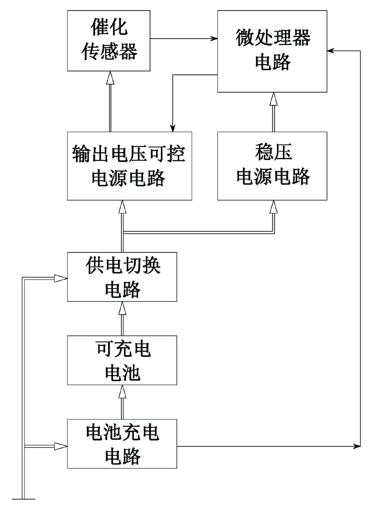
[0020] Such as figure 1 As shown, a combustible gas detector includes a microprocessor circuit, a catalytic sensor connected to the microprocessor circuit, an output voltage controllable power supply circuit, a regulated power supply circuit, a power supply switching circuit, a battery charging circuit and a Rechargeable Battery.

[0021] Wherein, the sensor voltage output end of the output voltage controllable power supply circuit is connected to the power supply end of the catalytic sensor to provide an operating voltage; the voltage control end of the microprocessor circuit is connected to the sensor voltage of the output voltage controllable power supply circuit Adjust the control terminal, so that according to the needs of sulfur removal, the microprocessor circuit controls the output voltage controllable power supply circuit, so th...


PUM


Abstract

The invention provides an inflammable gas detecting instrument and a desulphurization method thereof, wherein the detecting instrument comprises a microprocessor circuit, a catalytic sensor connected with the microprocessor circuit, and an output voltage controllable power supply circuit; a sensor voltage output end of the output voltage controllable power supply circuit is connected with a power source end of the catalytic sensor, and an voltage control end of the microprocessor circuit is connected with a sensor voltage adjustment control end of the output voltage controllable power supply circuit; the desulphurization method comprises the following steps: the microprocessor circuit controls the output voltage controllable power supply circuit for voltage adjustment; the output voltage of the sensor voltage output end is improved to 1.5 times of the normal working voltage and the time is delayed for 120s; the output voltage controllable power supply circuit is continued to be controlled so as to enable the output voltage of the sensor voltage output end to be zero or normal working voltage. The detecting instrument has the advantages of automatic desulphurization, accurate measuring result, safety and reliability; furthermore, the desulphurization method is simple and practical, and is easy to realize.

Description

technical field [0001] The invention relates to a gas detection instrument, in particular to a combustible gas detection instrument and a sulfur removal method thereof. Background technique [0002] Toxic and harmful gases in industrial and mining environments include hydrogen sulfide, sulfur dioxide, etc. To detect the existence of these gases, sensors based on the principles of infrared and catalytic combustion can be used; in practical applications, due to the high price of infrared sensors, catalytic sensors are usually used to detect these gases. detection. [0003] The catalytic combustion gas sensor uses its oxidative combustion characteristics to detect the content of combustible gases in the air. It is a sensor dedicated to combustible gases; the detection element of the catalytic element is a spherical coil covered with alumina and adhesive, and It is made by sintering, and its outer surface is covered with a catalytic layer of platinum, palladium and other rare m...

Claims


Application Information

Patent Timeline
IPC IPC(8): G01N27/16G01N1/28
Inventor 张小水常磊俎伟明刘宁刘鲜花
Owner HENAN HANWEI ELECTRONICS
Learn More