Ultrasonic transducer device for geometric shape array of planar corrosive defect

A technology of ultrasonic transducers and geometric shapes, applied in measuring devices, material analysis using sound waves/ultrasonic waves/infrasonic waves, instruments, etc., can solve the problems of low dynamic scanning efficiency and low configuration accuracy, and achieve simple and easy practical application Easy to use, high application value, and easy to modularize

Inactive Publication Date: 2012-06-20
BEIJING INSTITUTE OF TECHNOLOGYGY
View PDF7 Cites 3 Cited by
  • Summary
  • Abstract
  • Description
  • Claims
  • Application Information

AI Technical Summary

Problems solved by technology

[0012] The purpose of the present invention is to solve the above-mentioned ultrasonic detection method, the detection accuracy of the fixed probe is low, the geometric shape of the defect cannot be detected, the position of the dynamic ultrasonic C-scan transducer is not fixed, and the scanning motion mechanism needs to be added, which cannot adapt to industrial In order to solve the problem of remote dynamic monitoring of defects in the production field, a geometric shape array ultrasonic transducer device for planar corrosion defects is provided. Ultrasonic full coverage of components within the sensor array range, overcoming the problems of low precision of conventional probe configuration and low dynamic scanning efficiency

Method used


Image

  • Ultrasonic transducer device for geometric shape array of planar corrosive defect
  • Ultrasonic transducer device for geometric shape array of planar corrosive defect
  • Ultrasonic transducer device for geometric shape array of planar corrosive defect

Examples


specific Embodiment approach

[0037] combine figure 2 , image 3 , Figure 4 One embodiment of the present invention will be described.

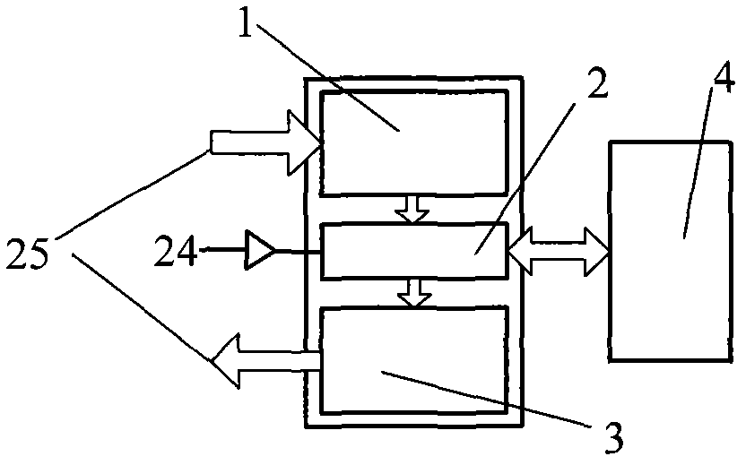
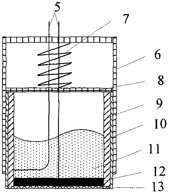
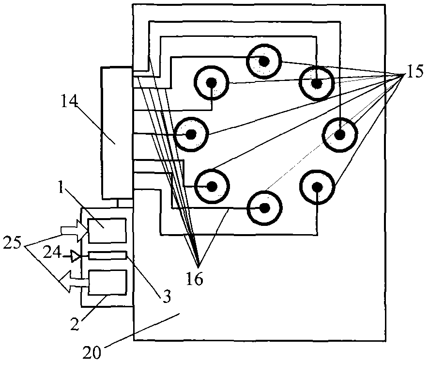
[0038] The present invention includes an excitation signal conditioning module 1, a multi-way switch 2, a receiving signal conditioning module 3, a piezoelectric transducer assembly (including a sliding sleeve 6, a preload spring, a transducer housing (8, 9, 10), a connecting Core wire 5, piezoelectric wafer 12, matching layer 13, backing layer 11), fixing bracket 20, external connecting wire 16, multi-way switch control wire 24, excitation and receiving signal wire 25.

[0039] refer to figure 2 As shown in the positional relationship, the matching layer 13 and the piezoelectric crystal sheet 12 are pasted together with glue, the piezoelectric crystal sheet 12 and the matching layer 13 are combined and installed at the lowermost end of the transducer, and the backing layer 11 is installed on the In the airtight cavity closed by the combination of the transducer no...


PUM


Abstract

The invention relates to an ultrasonic transducer device for a geometric shape array of a planar corrosive defect. The ultrasonic transducer device comprises a piezoelectric ultrasonic transducer group which is used for generating and receiving ultrasonic waves, a fixing bracket which is used for fixing piezoelectric transducers, a module which is used for exciting the operation of the piezoelectric transducers and adjusting a received signal and a multi-way switch which is for controlling the ultrasonic waves generated and received by the piezoelectric transducers, wherein the piezoelectric transducer group is fixed on the bracket according to a certain geometric location relationship to form a specific array device; and the piezoelectric transducers are flexibly connected with the fixing bracket through sliding sleeves and pre-tightening springs to realize close contact between each transducer and a piece to be detected. The ultrasonic transducer device for the geometric shape array of the planar corrosive defect, disclosed by the invention, has the advantages that: as the geometric shape array of the defect can be detected through fixing the transducers, high detection efficiency is obtained; as a sound field can cover all regions inside the array, high detection precision is obtained; as transducer configuration with uniform performance and type is adopted, modularization can be realized conveniently; and as the ultrasonic transducer device can be applied to the nondestructive detection of regular ultrasonic industry and occasions with special requirements, the ultrasonic transducer device is wide in application range.

Description

1. Technical field [0001] The invention belongs to the technical field of ultrasonic nondestructive testing. Specifically, the present invention relates to an ultrasonic transducer device, where the transducer device refers to a transducer array device matched with an ultrasonic detection method. 2. Background technology [0002] Containers for transporting and storing corrosive substances in oil, natural gas, and petrochemical industries, as well as planar shells such as ships and aircraft, are prone to corrosive defects on their inner and outer surfaces due to the influence of the operating environment, resulting in thinner walls. Under conditions, the existing defects may further lead to stress concentration and self-expansion, resulting in greater safety hazards. Therefore, timely and accurate detection of the geometric form of corrosive defects enables effective non-destructive evaluation of component reliability and service life and forecasting are of great significan...

Claims


Application Information

Patent Timeline
Patent Type & Authority Applications(China)
IPC IPC(8): G01N29/22G01N29/26
Inventor 徐春广李喜朋刘钊肖定国潘勤学赵新玉郝娟孟凡武周世圆宋文涛曹现东
Owner BEIJING INSTITUTE OF TECHNOLOGYGY
Why Eureka
Try Eureka