Intelligent power network controller and working method thereof

A smart grid and controller technology, applied in electrical components, circuit devices, AC network circuits, etc., can solve the problems of large calculation amount, high cost, large amount of information, etc., and achieve the effect of improving conversion speed and simple circuit.

Active Publication Date: 2012-06-20
常州电子研究所有限公司
View PDF2 Cites 8 Cited by
  • Summary
  • Abstract
  • Description
  • Claims
  • Application Information

AI Technical Summary

Problems solved by technology

[0005] In the existing smart grid controller, if the calculation is performed in the single-chip microcomputer according to the above mathematical model, since the calculation of the three-phase current needs to be performed, and there are root sign operations and division operations, the calculation amount is very large; if it is made into a table, the If the above-mentioned curves are discretized and stored in the ROM of the single-chip microcomputer, the amount of information will be very large, and the corresponding cost will be relatively high; therefore, how to solve the above-mentioned problems is a technical problem in the art

Method used


Image

  • Intelligent power network controller and working method thereof
  • Intelligent power network controller and working method thereof
  • Intelligent power network controller and working method thereof

Examples


Embodiment 1)

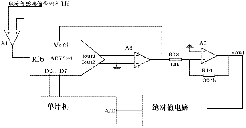
[0038] See figure 1 , the smart grid controller in this embodiment includes: a program-controlled amplifier, a current sensor connected to the current detection input terminal of the program-controlled amplifier, and a central control unit connected to the control input terminal of the program-controlled amplifier for controlling the amplification factor of the program-controlled amplifier unit; the current amplified signal output terminal of the program-controlled amplifier is connected to the current amplified signal detection input terminal of the central control unit.

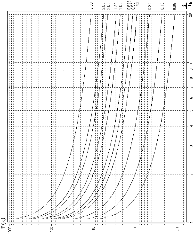
[0039] An inverse time overcurrent protection curve as a baseline is stored in the central control unit, and the time setting coefficient corresponding to the baseline is Tp 0 ; The time setting coefficient corresponding to the measured circuit where the current sensor is selected is Tp 1 .

[0040] The central control unit controls the magnification of the program-controlled amplifier to be Tp 0 / Tp 1...

Embodiment 2)

[0060] The working method of the smart grid controller based on the above-mentioned embodiment 1 includes the following steps:

[0061] A. There is an inverse time overcurrent protection curve as a baseline stored in the central control unit, and the time setting coefficient corresponding to the baseline is Tp 0 ;

[0062] B. Select the time setting coefficient corresponding to the measured line where the current sensor is located as Tp 1 ;

[0063] C, the central control unit controls the amplification factor of a program-controlled amplifier to be Tp 0 / Tp 1 , the program-controlled amplifier amplifies the current signal output by the current sensor Tp 0 / Tp 1 sent to the A / D terminal of the central control unit, and the central control unit checks the corresponding protection action time limit T on the baseline according to the magnitude of the current amplification signal output by the program-controlled amplifier. 0 ; Then calculate the actual protection action ti...


PUM


Abstract

The invention relates to an intelligent power network controller comprising a program-controlled amplifier, a current sensor, and a central controlling unit. A current amplification signal output terminal of the program-controlled amplifier is connected to the central controlling unit. An inverse-time over-current protection curve is stored as a baseline in the central controlling unit. A time setting coefficient corresponding to the baseline is Tp0. A time setting coefficient corresponding to a circuit requiring testing is Tp1, wherein the current sensor is in the circuit. An amplification multiple of the program-controlled amplifier is controlled at the value of Tp0/Tp1 by the central controlling unit. According to the volume of the current amplification signal outputted by the program-controlled amplifier, a corresponding protective action time limit T0 is retrieved on the baseline. An actual protective action time limit T1 is calculated according to a formula that Ti=(Tp1/Tp0)T0. Finally, according to the actual protective action time limit T1, the central controlling unit executes a protection action through a driving circuit connected to the central controlling unit, such that the tested circuit with the current sensor is cut off.

Description

technical field [0001] The invention relates to a smart grid controller and a working method thereof. Background technique [0002] Various faults and abnormal operating states may occur in the power system during operation. The most common and dangerous faults are short circuits in various forms. Short-circuit faults can destroy the stability of the power system and cause the entire system to collapse, causing large-scale power outages and often causing greater losses to the national economy. Therefore, it is a technical requirement in this field to automatically, rapidly and selectively cut off the faulty line from the power system to ensure the normal operation of other non-faulty parts. [0003] In the prior art, by sampling the load overcurrent and figure 1 The curve family of the current-time characteristic curve shown, obtains the protection action time limit of the grid controller. When the load overcurrent current is large, the time limit of the protection action...

Claims


Application Information

Patent Timeline
Patent Type & Authority Applications(China)
IPC IPC(8): H02J3/00H02H7/26
Inventor 王全忠
Owner 常州电子研究所有限公司
Why Eureka
Try Eureka