
Automatic calibrating and tracking system of driver sight line

A driver's line of sight, automatic calibration technology, applied in closed-circuit television systems, TV system components, TVs, etc., can solve the problems of weakening corneal reflection, not being able to complete well, uneven light, etc., to improve Accuracy, resolution of line-of-sight alignment and tracking challenges, and ease of operation

Inactive Publication Date: 2012-06-20
DALIAN MARITIME UNIVERSITY
View PDF8 Cites 41 Cited by
  • Summary
  • Abstract
  • Description
  • Claims
  • Application Information

AI Technical Summary

Problems solved by technology

Another major problem is that the above methods require a rigorous calibration process, such as requiring the observer to fixate on 6-12 different calibration points sequentially displayed on the screen in order to determine the vector between the pupil and the corneal reflection point and the fixation point on the screen. Correspondence between
This calibration process generally takes about 1-2 minutes to complete well, which is rather cumbersome.
[0003] In a real driving environment, the above method does not work well
For example, it is impossible to calibrate in the car, the driver's head has a large range of motion (observe the left and right rearview mirrors, and sometimes look backwards), the light is not uniform, especially the sunlight can weaken the reflection of the infrared light source on the cornea effect, so widely used infrared-based corneal reflectance methods are no longer effective in real driving environments

Method used


Image

  • Automatic calibrating and tracking system of driver sight line
  • Automatic calibrating and tracking system of driver sight line
  • Automatic calibrating and tracking system of driver sight line

Examples


Embodiment Construction

[0037] Now in conjunction with accompanying drawing, the present invention is described in further detail:

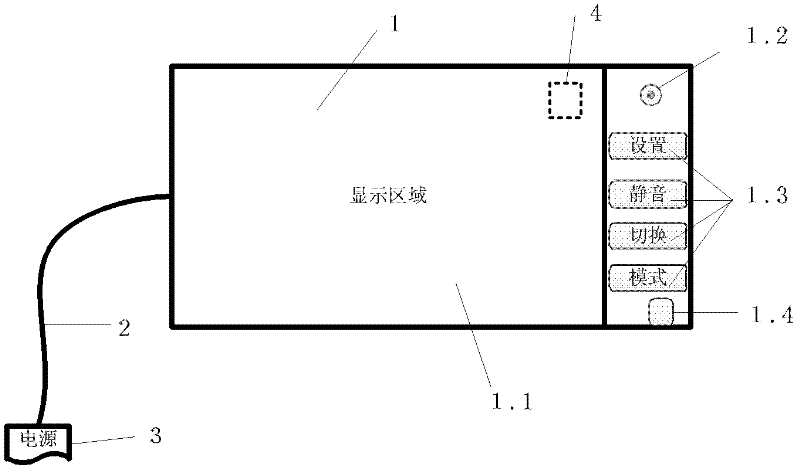
[0038] A driver's line of sight automatic calibration and tracking system, its device such as figure 1 As shown, the main body 1 of the device integrates input and output devices and processors, and a three-dimensional accelerometer 4 is installed inside. The image or gaze point area captured by the camera.

[0039] Multiple buttons 1.3 can be set on the side of the display screen, including the "Setting" button, which is used to set the input and output methods and content, such as inputting camera parameters (focal length, resolution, etc.), outputting images and gaze point areas, etc., or outputting real-time line of sight Tracking accuracy curve, etc.; including "switch" button, used to switch input and output content; including "mode" button, used to select calibration mode, operation mode and image information display mode; including "mute" button, used to contro...


PUM


Abstract

The present invention relates to an automatic calibrating and tracking system of driver sight line capable of combining a driver head position with a vehicle key part information and automatically calibrating the driver sight line. The driver sight line calibrating process of the system not has the calibrating point setting and sight line justifying process and the automatic calibrating and tracking system automatically calibrates the driver sight line according to the driver head position information and the relative position of the correlative components such as a vehicle rearview mirror and an instrument panel during the driving process. In order to increase the identification effect of the head feature, a light source system is automatically controlled according to the variance in the outside light intensity, namely when in the daytime and the light ray is relatively good, the visible light is used to identify and when in the night and the light ray is relatively weak, an infrared light source is used. The influence on identifying the head feature by vehicle head lights is avoided by the infrared light source in the night. The automatic calibrating and tracking system has important value on aspects such as driver attention research and fatigue drive based on sight line.

Description

technical field [0001] The invention relates to a driver's line of sight automatic calibration and tracking system, in particular to an algorithm and a device for collecting key component position information of people and vehicles and determining the driver's gaze point position through statistical and learning methods. Background technique [0002] Driver's gaze tracking is of great significance to the study of driver's attention and fatigue. However, due to the traditional line-of-sight technology has certain restrictions on head movement, light or application scenarios, such as the most widely used pupil cornea reflection method based on infrared light sources, in order to achieve higher accuracy, the human head must not Move (fix the head with chin rest and other methods); in order to ensure the stability of light and avoid the influence of sunlight, infrared light sources are generally used and carried out indoors; the target of sight tracking is also relatively certai...

Claims


Application Information

Patent Timeline
IPC IPC(8): H04N7/18H04N5/232G06T7/20B60R11/04
Inventor 付先平袁国良
Owner DALIAN MARITIME UNIVERSITY
Learn More