

Extrusion soil breaker
A crusher and extrusion technology, applied in the field of mechanical equipment, can solve problems affecting workers' health, high labor intensity, complex equipment, etc., and achieve the effect of simple structure, low cost and low noise
- Summary
- Abstract
- Description
- Claims
- Application Information
AI Technical Summary
Problems solved by technology
Method used
Image

Examples
Embodiment Construction
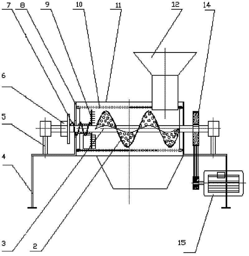
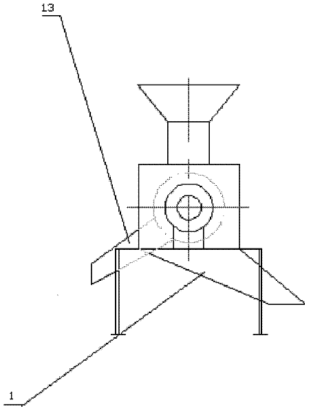
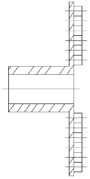
[0014] Such as Figure 1-5 As shown in the figure, an extruding soil clod breaker includes a frame, left and right wallboards arranged on the frame, auger shafts passing through the left and right wallboards and supported by bearing seats, and fixed on the left and right wallboards A casing with a material inlet and outlet and a pulley set on the auger shaft driven by a motor. The auger blades 2 on the 11 auger shafts 3 in the casing are evenly distributed with scrap claws, and the sieve cylinder 10 connected to the left and right wallboards 8 is arranged between the auger blades and the radial direction of the casing. The screen drum is composed of two semicircular thick steel plates, and the screen drums made of thick steel plates are provided with screen holes of the same diameter. The gap between the auger blade and the screen drum is consistent. The auger shaft in the screen cylinder is equipped with a pressure plate 9 with pressure claws 18 evenly distributed in the ci...
PUM
 Abstract
Description
Claims
Application Information