
Waste plastic sand remover

A technology of waste plastics and sand machines, which is applied in the direction of solid separation, classification, chemical instruments and methods, etc. It can solve problems such as mechanical failure, sewage impact, and high water dependence, achieve low manufacturing and maintenance costs, and improve sand removal efficiency. , long service life effect

Inactive Publication Date: 2012-06-27
SHANGHAI SHENJIA SANWA +1
View PDF5 Cites 10 Cited by
  • Summary
  • Abstract
  • Description
  • Claims
  • Application Information

AI Technical Summary

Problems solved by technology

These methods are highly dependent on water, the waste of water resources is serious, and the sewage produced has a certain impact on the environment.
For the method of stirring and cleaning, the plastic is easy to wrap around the blade of the stirring shaft, causing mechanical failure
In addition, these methods all have the problem of discontinuous cleaning process. After a batch of materials are cleaned and discharged, another batch of materials needs to be placed

Method used


Image

  • Waste plastic sand remover
  • Waste plastic sand remover
  • Waste plastic sand remover

Examples


Embodiment 1

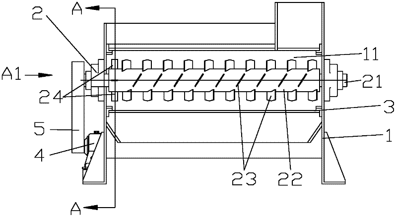
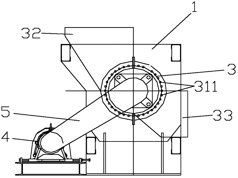
[0025] figure 1 It is a schematic structural view of an embodiment of the waste plastic sand removal machine of the present invention, figure 2 For the waste plastic desanding machine of the present invention figure 1 Schematic diagram of the structure in the direction shown in A1. Such as figure 1 with figure 2 As shown, the waste plastic desanding machine of the present invention includes a frame 1 , a spiral part 2 , a grid 3 and a transmission part 4 . In this embodiment, the transmission part 4 is a motor, which drives the screw part 2 to move through a V-belt 5 and a V-shaped pulley.

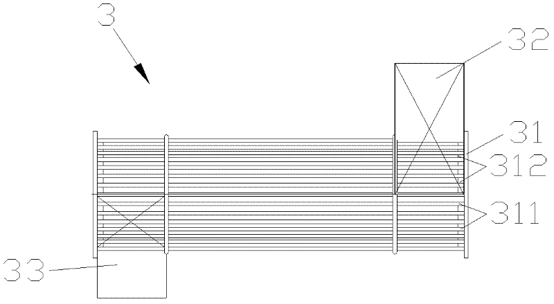
[0026] The frame 1 includes an accommodating inner cavity 11, and a grid 3 is arranged in the cavity. image 3 It is the structural representation of the grid of the waste plastic desander of the present invention, as image 3 In the present embodiment shown, the grid 3 includes a cylindrical body 31, on which several grid pieces 311 are arranged, and the gap 312 between each grid ...

Embodiment 2

[0030] With regard to the waste plastic desand remover provided in Example 1, the removal of sediment attached to waste plastics was studied by using different pitches and conveying blade specifications, see Table 1.

[0031] The calculation method of sediment removal amount is as follows:

[0032] Properly heat the waste plastic to a constant weight to remove the moisture contained in the sediment, and record the value obtained by weighing as W0, then put it into the waste plastic desanding machine to stir and remove sand, weigh the discharged waste plastic and heat it to constant weight. Weight, the value obtained by weighing is recorded as W1, and the discharged waste plastic is manually desanded, heated to constant weight, and the value obtained by weighing is recorded as W2. Sand removal rate%=(W0-W1)×100% / (W0-W2).

[0033] It can be seen from Table 1 that the increase of the screw pitch and the suitable specification of the blade can significantly increase the sand remo...


PUM


Abstract

The invention provides a waste plastic sand remover comprising a machine rack, a grid, a spiral component and a transmission component. Transmission equipment is connected with spiral equipment so as to drive the spiral equipment to rotate. The spiral equipment is sleeved in the grid. A plurality of transmission blades and a plurality of discharging blades are arranged on the spiral equipment so as to remove sediment substances adhered to waste plastics. The waste plastic sand remover disclosed by the invention has the advantages of simple equipment structure, reliability in operation, low manufacture and maintenance cost and long service life. Meanwhile, the waste plastic sand remover can be used for continuous feeding and discharging and is high in sand-removal efficiency.

Description

technical field [0001] The invention relates to a material cleaning device, in particular to a waste plastic sand remover specially used for removing sand from recycled waste plastics, so as to facilitate subsequent crushing of plastics. Background technique [0002] Usually, in the various links of the use and recycling of plastic products, there will be some sediment adhered or wrapped on the surface of the recycled waste plastics. In consideration of circular economy, waste plastics are further pelletized after recycling, so that they can be reused. In order to facilitate the granulation process, generally the recovered waste plastics must be crushed first, and then cleaned and dried in turn before being used for granulation. [0003] During the plastic crushing process, the sand, mud and pebbles adhered to the waste plastic will seriously damage the cutter of the crusher, making the cutter blunt faster (it will wear out in about a week and needs to be disassembled and r...

Claims


Application Information

Patent Timeline
Patent Type & Authority Applications(China)
IPC IPC(8): B07B13/04
Inventor 刘璞张健林炳锵
Owner SHANGHAI SHENJIA SANWA
Learn More