
Loading and unloading transmission device for machine tool

A material feeding and machine tool technology, which is applied in the field of machine tool loading and unloading and feeding devices, can solve the problems of not being able to grab workpieces, instability, shaking, etc., and achieve the effects of reducing labor intensity, convenient production, and simple structure

Active Publication Date: 2012-06-27
CHONGQING MACHINE TOOL GROUP
View PDF10 Cites 7 Cited by
  • Summary
  • Abstract
  • Description
  • Claims
  • Application Information

AI Technical Summary

Problems solved by technology

Because the instantaneous transmission ratio of the roller chain is unstable, and the workpiece bracket holding the workpiece is connected with the roller chain, this will cause the workpiece bracket to shake when it stops and moves, resulting in the workpiece bracket staying at the correct position. There is a certain error in the grabbing position, which leads to a certain error between the stop position of the workpiece and the correct grabbing position. There are two problems when the material claw of the machine tool moves down to grab the workpiece: first, the material claw of the machine tool grabs The workpiece is difficult and unstable, and even the workpiece cannot be grasped, which will affect the normal operation of the machine tool; second, the material claw will have a relatively large rigid impact with the workpiece, and even damage the material claw
At the same time, the defect of the traditional silo device when loading materials is that it is difficult for the claws to accurately place the workpiece on the workpiece holder when unloading the material.
In addition, the automatic loading and unloading device of the traditional machine tool is relatively high, and it is not very convenient for workers to operate when loading and unloading workpieces. Therefore, it is urgent to solve the above technical problems

Method used


Image

  • Loading and unloading transmission device for machine tool
  • Loading and unloading transmission device for machine tool
  • Loading and unloading transmission device for machine tool

Examples


Embodiment Construction

[0019] Below in conjunction with accompanying drawing and embodiment the present invention will be further described:

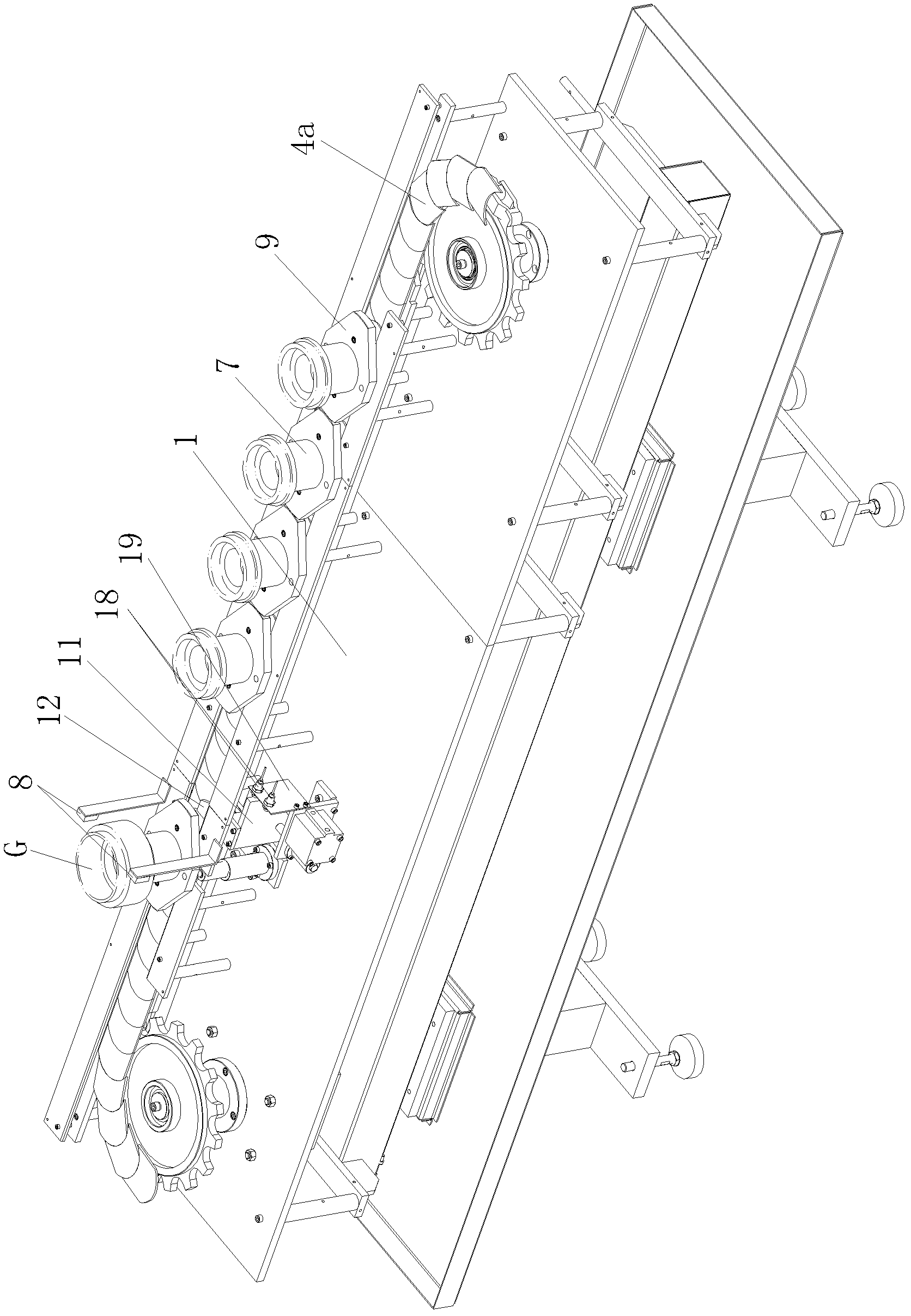
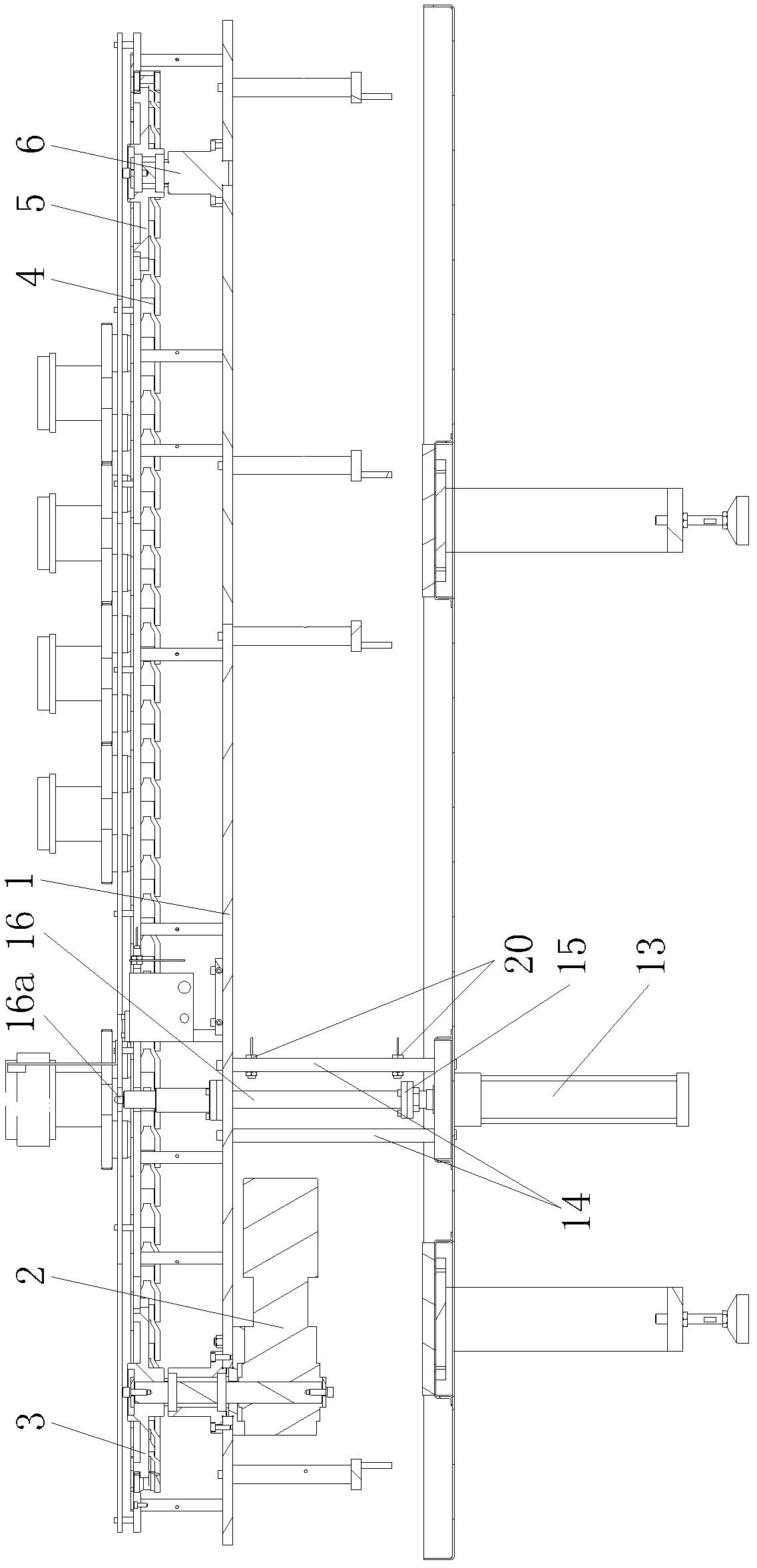
[0020] Such as Figure 1-5 As shown, the present invention mainly consists of an intermediate plate 1, a reducer 2, a driving sprocket 3, a warp chain 4, a driven sprocket 5, a vertical support shaft 6, a workpiece bracket 7, a shooting switch 8, a pallet 9, and a cylinder 10. Vertical plate 11, horizontal baffle plate 12, oil cylinder 13, side plate 14, horizontal plate 15, push rod 16, small cylinder 17, first proximity switch 18, vertical mounting plate 19, second proximity switch 20 and The cylinder mounting plate 21 is formed, wherein the reducer 2 is hoisted on the left part of the middle plate 1, the reducer 2 is the power source of the bin device, and the upper end of the output shaft of the reducer 2 is coaxially fitted with the active chain Wheel 3, the driving sprocket 3 is connected with the driven sprocket 5 through the chain 4. The above-menti...


PUM


Abstract

The invention discloses a loading and unloading transmission device for a machine tool. The loading and unloading transmission device comprises a speed reducer on the left part of an intermediate plate, wherein a driving chain wheel on the upper end part of an output shaft of the speed reducer is connected with a driven chain wheel by a chain; a pair of correlation switches for acquiring signals of a workpiece bracket reaching a grabbing position is arranged above the chain; a tray is arranged on a support top plate of the chain; the workpiece bracket is arranged on an upper tray; an air cylinder is arranged on the intermediate plate from front to back; and the rear end part of an air cylinder extension bar is provided with a horizontal baffle capable of blocking the tray by a vertical plate. According to the loading and unloading transmission device, a workpiece is driven by friction force to move with the chain and is blocked reliably by the horizontal baffle, and the retention position of the workpiece is fixed and accurate, so that a bunker device is matched with a feed claw of the machine tool to load and unload; and the workpiece is jacked by the loading and unloading transmission device according to requirements to reduce the integral height of the bunker device effectively, so that the workpiece is put on the workpiece bracket by workers, and the loading and unloading transmission device has a simple structure and is convenient to manufacture.

Description

technical field [0001] The invention relates to an accessory equipment of a machine tool, in particular to a machine tool loading and unloading and feeding device. Background technique [0002] The existing machine tool loading and unloading feeding device adopts general roller chain transmission, and the roller chain is driven by a reducer; the workpiece is placed on the workpiece holder, and the workpiece holder is connected with the roller chain. Driven by the reducer, the workpiece moves together with the workpiece holder and the roller chain. Moreover, a proximity switch (a pair of through-shooting switches can also be used) is provided on the bin device, and the proximity switch is used to detect the situation that the workpiece G reaches the gripping position. When the proximity switch detects the in-position signal of the workpiece, the numerical control system of the machine tool controls the reducer to stop working, so that the roller chain and the workpiece stop ...

Claims


Application Information

Patent Timeline
IPC IPC(8): B23Q7/00
Inventor 李先广陈伦安孙百超王庆科高槐陈志强
Owner CHONGQING MACHINE TOOL GROUP
Learn More