Composite swirl combustion chamber

A technology of combustion chambers and composite rolls, applied in combustion engines, internal combustion piston engines, machines/engines, etc., can solve problems such as low air utilization, poor oil-gas mixing, and reduced fuel injection penetration, and achieve fuel distribution expansion, The effect of high air utilization rate, mixing and accelerated combustion

Inactive Publication Date: 2012-06-27
BEIJING INSTITUTE OF TECHNOLOGYGY
View PDF3 Cites 4 Cited by
  • Summary
  • Abstract
  • Description
  • Claims
  • Application Information

AI Technical Summary

Problems solved by technology

Fuel high-pressure injection technology can quickly atomize fuel in zone 2 after injection, which can better solve the problem of fuel-air mixing speed, but there is only a small amount of fuel in the far end of zone 3, zone 4 and zone 1 below the fuel jet in the combustion chamber. The air utilization rate is low, even if the injection penetration is increased or the angle of the oil beam is increased, the air utilization rate of the 3rd and 4th areas will only be improved; although the combustion chamber and swirl optimization matching technology can comprehensively optimize the , gas mixture, but because the vortex reduces the penetration of the oil beam, the 3rd and 4th areas become worse, and the fuel in the 1st area can hardly reach, and the diffusion of the fuel in the process of the piston moving down still cannot make full use of these areas. Air; while the turbocharged intercooler technology actually relies on increasing the air intake density and the oil supply system to increase the circulating fuel injection volume to achieve the purpose of increasing power and reducing fuel consumption. The increase in air density will lead to a decrease in fuel injection penetration. , so that the air utilization rate in the far end of zone 3 in the combustion chamber and in zone 4 of the squeeze zone decreases, and in zone 1, because of the small amount of fuel, the mixture of oil and gas is very poor
To sum up, at present, these technical means only focus on the mixing of oil and gas in a certain space of the combustion chamber, but cannot fully consider the even distribution of fuel oil in the entire space of the combustion chamber.

Method used


Image

  • Composite swirl combustion chamber
  • Composite swirl combustion chamber
  • Composite swirl combustion chamber

Examples


specific Embodiment

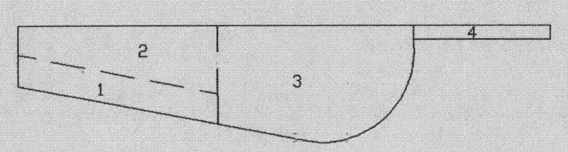
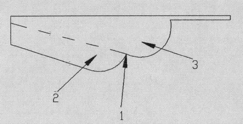
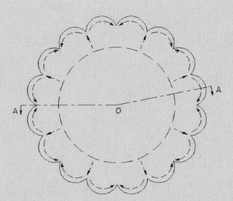
[0038] The CFD three-dimensional mesh models of the composite plume combustor, ω combustor, double plume combustor and side plume combustor under the same compression ratio were respectively established for simulation calculation comparison. Among them, the structures of the basic double-plume combustor, ω combustor, double-plump combustor and side swirl combustor are determined by parametric design.

[0039] The design parameters and calculation settings of the combustion chamber are: eight-hole fuel injector is suitable, the cylinder diameter is 132mm, the stroke is 145mm, the connecting rod length is 262mm, and the clearance height is 2.5mm.

[0040] Calculated according to the compression ratio of 13.5, the volume of the compound plume combustion chamber should be 107510mm 3 . The actual modeling volume is 106506mm 3 , with a deviation rate of 0.93%. In terms of geometric dimensions, the center cone angle is 119°, the cone point height is 5.4mm, the depth of the outer c...


PUM


Abstract

The invention relates to a composite swirl combustion chamber structure, which is composed of a base double swirl combustion chamber and a side swirl combustion chamber tip shunting structure laminated at the outer edge of the combustion chamber. According to the invention, on one hand, the structure characteristics of the double swirl combustion chamber are utilized, so that fuel forms swirls with opposite directions in inner and outer chambers; on the other hand, an outer chamber fuel collision tip shunting structure is utilized, so that the fuel generates lateral swirl, and the fuel is accelerated to be diffused to the total space of the combustion chamber, thus the fuel and air are more uniformly mixed, the utilization rate of air is improved, the requirement on intake swirl is correspondingly reduced, and the power performance, economy and emission performance of the engine are improved to a certain extent. The key to the invention is matching between the geometrical sizes of the base double swirl combustion chamber and the tip shunting structure and the included angles of fuel pockets, and the laminated tip shunting structure is simple and feasible.

Description

technical field [0001] The invention relates to a specially designed and processed diesel engine combustion chamber. The combustion chamber is superimposed on the basis of a double plume flow combustion chamber with a suitable number of side plume tip split flow shapes. The fuel sprayed from the nozzle hole of the injector is first Hitting the double plume arc ridge forms two-way plumes respectively in the inner chamber and the outer chamber, and the fuel distributed to the outer chamber hits the tip splitter shape and spreads to both sides of the splitter shape to form two lateral plumes. The combustor combines the advantages of high air utilization rate of the double plume combustor and the side swirl combustor, accelerates the mixing rate of oil and gas through the action of the double swirl flow, and achieves the purpose of improving the combustion performance and emission performance of the diesel engine. Background technique [0002] The fuel fragmentation and oil-air ...

Claims


Application Information

Patent Timeline
Patent Type & Authority Applications(China)
IPC IPC(8): F02B23/00
CPCY02T10/125Y02T10/12
Inventor 李向荣苏立旺刘福水尚勇赵陆明
Owner BEIJING INSTITUTE OF TECHNOLOGYGY
Why Eureka
Try Eureka