Distributed stress/temperature sensing optical fiber coordinate locating device

A technology of distributed strain and sensing optical fiber, which is applied in the direction of physical/chemical change thermometers, thermometers, measuring devices, etc., can solve problems such as difficult correspondence, measurement position deviation, elongation, etc., to facilitate handling and reduce measurement The effect of error and accuracy improvement

Inactive Publication Date: 2012-06-27
CHINA FIRST METALLURGICAL GROUP +1
View PDF5 Cites 19 Cited by
  • Summary
  • Abstract
  • Description
  • Claims
  • Application Information

AI Technical Summary

Problems solved by technology

However, the optical fiber sensing points in one-dimensional coordinates also bring difficulties to the three-dimensional spatial positioning of the measured structure
The data obtained by the distributed sensing optical fiber measurement is meaningful only when it is accurately projected on the measured structure. However, the actual situation is that although most distributed sensing optical fibers are marked with one-dimensional coordinates, the surface has no Label the length coordinates (or the labeling accuracy is more than 1 meter, which cannot meet the requirements for accurate positioning of the coordinates), so it is difficult to correspond to the specific position of the measured structure. Even if there are a small number of centimeter-level length labels for distributed sensing fibers, It will be difficult to meet the measurement accuracy requirements due to the following factors:
[0004] 1. The distributed sensing optical fiber is laid in the structure, usually the surface of the optical fiber will be completely wrapped by glue and other protective materials, so that the coordinate positioning cannot be performed by reading the marked length
[0005] 2. The optical fiber is elongated due to pretension during laying, or the length changes due to other factors, which will cause the difference between the actual length and the marked length, and eventually cause the deviation of the measurement position;
[0006] 3. The difference between the actual length and the marked length of the measuring line composed of distributed sensing optical fibers can no longer be calculated after multiple connections, so it is difficult to carry out precise coordinate positioning in space;
[0007] 4. The positioning error of the signal demodulator will expand as the length of the optical fiber increases, resulting in the inconsistency between the theoretical coordinates of the measurement point and the marked coordinates during long-distance measurement, making the marked coordinates unavailable
[0008] In view of the above reasons, the difficulty of coordinate positioning has reduced the measurement accuracy of distributed sensing optical fiber, so a new technology is urgently needed to accurately determine the coordinates of the optical fiber measurement point corresponding to the specific position of each measured structure

Method used


Image

  • Distributed stress/temperature sensing optical fiber coordinate locating device
  • Distributed stress/temperature sensing optical fiber coordinate locating device
  • Distributed stress/temperature sensing optical fiber coordinate locating device

Examples


Embodiment 1

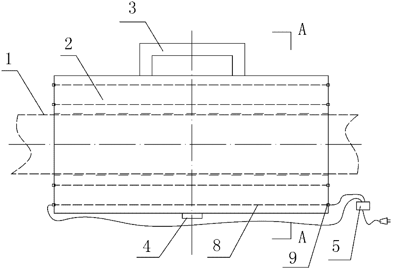
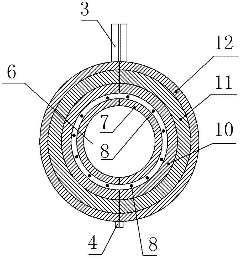
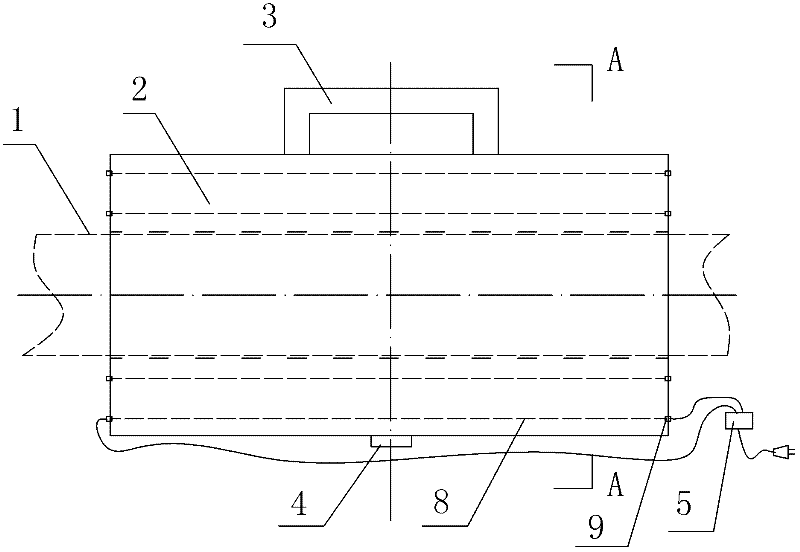
[0021] Such as figure 1 , figure 2 As shown, the distributed strain / temperature sensing optical fiber coordinate positioning device includes two semicircular ring members 2 (that is, 2 semicircular ring members 2), and the bottom ends of the two semicircular ring members are buckled by ordinary buckles. The upper ends of the two semicircular ring-shaped components are connected in a common buckle-and-latch manner (the upper ends are equipped with handles 3), and the two semicircular ring-shaped components form an optical fiber through the The ring structure of hole 6, the inner radius of two semicircular ring members is 1cm (the inner diameter of ring structure is 2cm), the outer radius of two semicircle ring members is 3cm (the outer diameter of ring structure is 6cm), two The length of the semicircular annular member is 25cm; Two semicircular annular members comprise outer skin and inner surface layer 7, and inner surface layer is positioned at outer skin (adopt plug-in co...

Embodiment 2

[0032] It is basically the same as Embodiment 1, except that the length of the two semicircular ring members is 5 cm.

[0033] Experiments were carried out according to the method described in Example 1, and the results showed that the accuracy rate reached 100%.

Embodiment 3

[0035] Basically the same as embodiment 1, the difference is: the inner radius of the two semicircular ring members is 0.3cm, the radius of the semicircle ring iron sheet is 1cm, and the outer radius of the two semicircle ring members is 2cm.

[0036] Experiments were carried out according to the method described in Example 1, and the results showed that the accuracy rate reached 100%.


PUM

PropertyMeasurementUnit
radiusaaaaaaaaaa
radiusaaaaaaaaaa
diameteraaaaaaaaaa

Abstract

The invention relates to a locating device capable of measuring corresponding coordinate position of a distributed sensing optical fiber in a measured structure. A distributed stress/temperature sensing optical fiber coordinate locating device is characterized in that the locating device comprises two semi-circle annular members, wherein the bottom ends of two semi-circle annular members are connected in a buckling manner; the upper ends of two semi-circle annular members are connected in a buckling manner; two semi-circle annular members form an annular structure with an optical fiber through hole inside; two semi-circle annular members comprise outer surface layers and inner surface layers; the inner surface layers are arranged in the outer surface layers; an electric heating wire is arranged between each outer surface layer and each inner surface layer; a lead wire connected with a wire connection head of each electric heating wire is respectively connected with a corresponding output end point in a power supply control box; each outer surface layer is composed of an iron layer, an asbestos layer and a ceramic layer, which are arranged from inside to outside; and each inner surface layer is a glass layer. According to the method, a measurement circuit composed of the distributed sensing optical fiber can be subjected to accurate coordinate location.

Description

technical field [0001] The invention belongs to the technical field of distributed optical fiber sensing in optoelectronic technology, and specifically relates to a positioning device capable of measuring the corresponding coordinate position of a distributed sensing optical fiber in a measured structure. Background technique [0002] Brillouin Optical Time Domain Analyzer (BOTDA) is a technology that uses the frequency change of light scattered in the optical fiber to measure the change of optical fiber strain (temperature). It can measure temperature and strain simultaneously. Its working principle is: The laser transmitters at both ends of the fiber inject a beam of pulsed light and a beam of continuous light into the fiber respectively. When the frequency difference between the pulsed light and the continuous light is equal to the Brillouin frequency shift of a certain interval in the fiber, the area will be affected. Exciting the Brillouin amplification effect, energy t...

Claims


Application Information

Patent Timeline
Patent Type & Authority Applications(China)
IPC IPC(8): G01K11/32G01L1/24G01K11/322
Inventor 王平刘建辉丁勇
Owner CHINA FIRST METALLURGICAL GROUP
Why Eureka
Try Eureka