Compact catadioptric long-wave infrared athermal imaging optical system

A long-wave infrared, optical system technology, applied in the optical field, can solve the problems of small field of view, short focal length, large volume, etc., and achieve the effect of large field of view, long focal length imaging, and compact structure

Inactive Publication Date: 2012-06-27
CHANGCHUN INST OF OPTICS FINE MECHANICS & PHYSICS CHINESE ACAD OF SCI
View PDF6 Cites 32 Cited by
  • Summary
  • Abstract
  • Description
  • Claims
  • Application Information

AI Technical Summary

Problems solved by technology

Since both the primary and secondary mirrors of the optical system are mirrors, the focal length is short, the field of view is small, and the volume is large.

Method used


Image

  • Compact catadioptric long-wave infrared athermal imaging optical system
  • Compact catadioptric long-wave infrared athermal imaging optical system
  • Compact catadioptric long-wave infrared athermal imaging optical system

Examples


Embodiment Construction

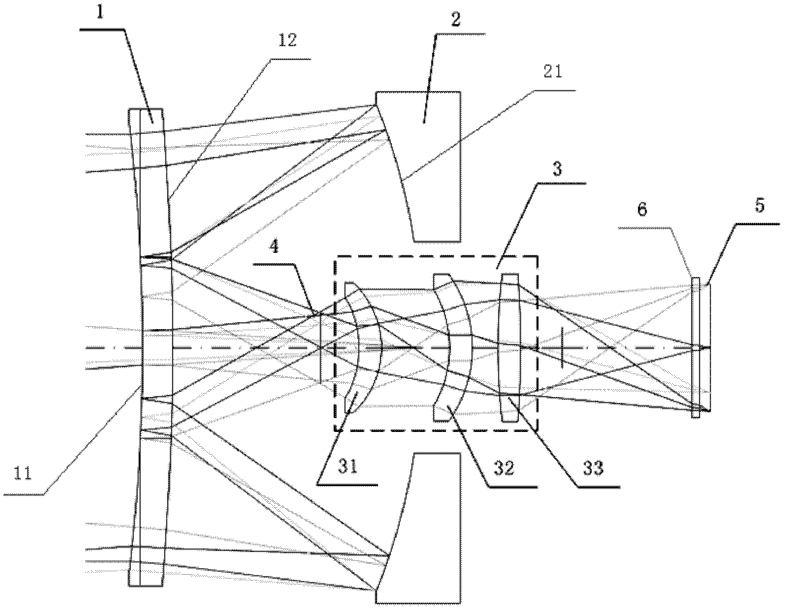
[0024] like figure 1 , 2 As shown, the compact catadioptric long-wave infrared athermalized imaging optical system of the present invention is composed of a secondary mirror 1 , a primary mirror 2 and a relay mirror 3 in sequence from the object side to the image side. The imaging receiver adopts an area array long-wave infrared detector, which is used for imaging thermal radiation of 8 μm to 12 μm in the electromagnetic spectrum.

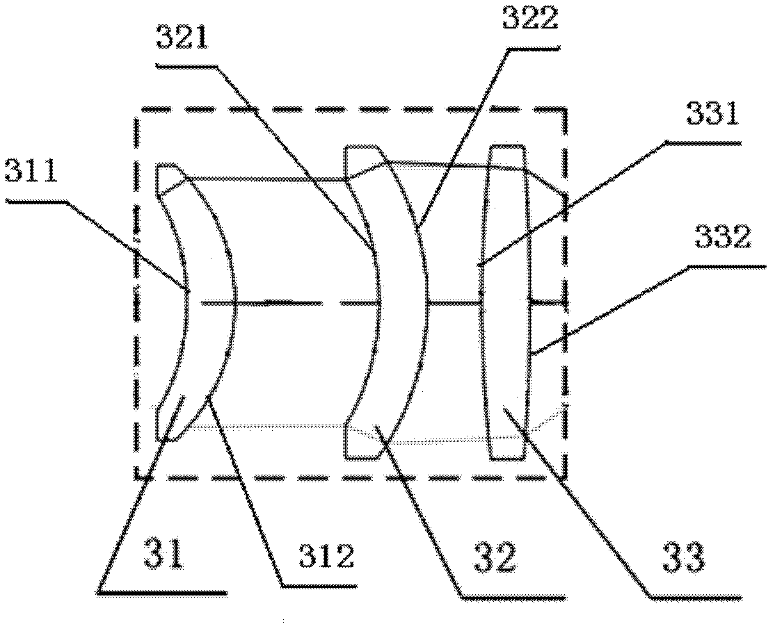
[0025] The optical system of the present invention is arranged in an orderly manner according to the xyz right-handed space coordinate system, the z-axis direction is defined as the optical axis direction, and the y-axis is at figure 1 In the plane shown, the x-axis is perpendicular to the yz plane, and the yz coordinate plane is the meridian plane of the optical system, see image 3 .

[0026] All optical elements of the system are arranged on the same optical axis, the reflective surface 21 of the primary mirror 2 is arranged opposite to the r...


PUM


Abstract

The invention relates to a compact catadioptric long-wave infrared athermal imaging optical system, which comprises a secondary lens, a primary reflective lens and a relay lens. The secondary lens is a catadioptric optical component with negative focal power and comprises an annular light transmission part and a central Mangin mirror; a light beam from an object is transmitted into the primary reflective lens through the annular light transmission part of the secondary lens and is then transmitted into the Mangin mirror of the secondary lens after reflection by the primary reflective lens, and catadioptric focusing is carried out by the Mangin mirror so that the target is imaged on a first image plane; the target on the first image plane is then transferred by the relay lens and focuses again on a second image plane; and the second image plane is overlapped with the focal plane of an image receiver. Image of long focal length can be realized, and the system has a compact structure and a large view field and can be applied in the optical imaging field of aviation and aerospace.

Description

Technical field: [0001] The invention belongs to the field of optical technology, and relates to a compact catadioptric long-wave infrared athermalization imaging optical system. Background technique: [0002] Infrared optical systems are used more and more widely, the working environment is more and more complex, and the imaging quality requirements of infrared optical systems are getting higher and higher. It is inevitable to design high-performance infrared optical systems that can work under harsh environmental conditions. Changes in ambient temperature will cause changes in the refractive index of materials, changes in the focal length of the system, image plane displacement (defocus), and deterioration of imaging quality. The thermal instability of this kind of optical system is especially serious for infrared optical systems, which is mainly due to the poor thermal stability of infrared optical materials, and the refractive index of most infrared optical materials cha...

Claims


Application Information

Patent Timeline
Patent Type & Authority Applications(China)
IPC IPC(8): G02B17/08G02B13/18G02B1/02
Inventor 张新王灵杰
Owner CHANGCHUN INST OF OPTICS FINE MECHANICS & PHYSICS CHINESE ACAD OF SCI
Why Eureka
Try Eureka