Building method for universal comprehensive models of single-rotor helicopters and turboshaft engines

A technology of turboshaft engine and construction method, which is applied in general control systems, simulators, control/regulation systems, etc., can solve the problem that the simplified model cannot fully and accurately reflect the dynamic and static characteristics of the engine, and reflect the nonlinear dynamic and static characteristics of the helicopter/engine Features, no substantive breakthroughs in the engine, etc.

Inactive Publication Date: 2012-06-27
NANJING UNIV OF AERONAUTICS & ASTRONAUTICS
View PDF3 Cites 38 Cited by
  • Summary
  • Abstract
  • Description
  • Claims
  • Application Information

AI Technical Summary

Problems solved by technology

[0003] Found through document retrieval to prior art, Wang Zhifeng et al. published "the establishment of helicopter flight/propulsion comprehensive model" on the 4th issue of the 17th volume of "Flight Mechanics" in 1999, and the helicopter model and the engine model in this paper all use linear It is difficult to reflect the nonlinear dynamic and static characteristics of the helicopter/engine within the large envelope range; the State Key Laboratory of Rotor of Nanjing University of Aeronautics and Astronautics has done in-depth research on helicopter/engine power matching in recent years, such as Chen Renliang 1998 doctoral dissertation "Helicopter Flight Dynamics Mathematical Modeling and Maneuverability Research", Sun Chuanwei's 2002 doctoral thesis "Helicopter Flight Dynamics Model and Flight Quality Evaluation", etc., but these achievements only re

Method used


Image

  • Building method for universal comprehensive models of single-rotor helicopters and turboshaft engines
  • Building method for universal comprehensive models of single-rotor helicopters and turboshaft engines
  • Building method for universal comprehensive models of single-rotor helicopters and turboshaft engines

Examples


Embodiment Construction

[0063] The technical scheme of the present invention is described in detail below in conjunction with accompanying drawing:

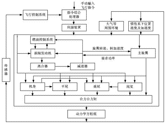
[0064] This specific embodiment takes the construction of the Black Hawk UH-60A helicopter / T700 turboshaft engine integrated system as an example, as figure 1 As shown in the structural diagram of the general simulation model of helicopter / turboshaft engine, it mainly includes the helicopter subsystem and the engine subsystem coupled with each other. Unsteady, nonlinear aerodynamic models of fuselage, tail rotor, horizontal and vertical tails. Among them, the rotor model is established based on the blade element theory, and a non-uniform first-order harmonic inflow model is adopted, which can accurately reflect the nonlinear and unsteady dynamic behavior of the rotor such as flapping and shimmy. The turboshaft engine component-level model is a nonlinear real-time mathematical model established by the component method, and can simulate the adjustable fu...


PUM


Abstract

The invention discloses a building method for the universal comprehensive models of single-rotor helicopters and turboshaft engines. The method includes the building of the non-linear models of a helicopter and an engine, the static trimming of the single-rotor helicopter and the turboshaft engine, the dynamic calculation of the single-rotor helicopter and the turboshaft engine and the actual operation solution of the single-rotor helicopter and the turboshaft engine, wherein the static trimming adopts the Levenberg-Marquarat algorithm, the dynamic calculation adopts the fourth-order Ronge-Kutta method to solve the motion equation system of the helicopter and the single pass algorithm to solve the dynamic balance equation of the turboshaft engine, and the actual operation state solution adopts a modified linear quadratic regulator algorithm to carry out helicopter solution and a cascade PID (Proportion-Integration-Differentiation) plus torque feedforward plus collective pitch compensation and torsional vibration filter method to carry out engine solution and load filtration. The method can meet the test requirements of the universal models and control methods of the single-rotor helicopters and the turboshaft engines, and plays an active role in helping to shorten the development cycle and reduce the test risk and the cost.

Description

technical field [0001] The invention belongs to the field of system control and simulation in aerospace propulsion theory and engineering, and specifically relates to a method for constructing a general comprehensive model of a single-rotor helicopter / turboshaft engine. Background technique [0002] In the field of aviation, digital simulation has developed into an indispensable part of complex system design and verification, and it is the most important part. Through digital simulation verification, the risk and cost of physical tests can be effectively reduced, and the development cycle can be greatly shortened. Helicopter is a high-order system with multiple degrees of freedom and strong coupling, including helicopter subsystem, engine subsystem and control system, etc. Its stability, maneuverability and maneuverability are worse than those of fixed-wing aircraft. With the new generation of Helicopters have continuously improved requirements for maneuverability, survivabi...

Claims


Application Information

Patent Timeline
IPC IPC(8): G05B17/02
Inventor 张海波王健康陈国强
Owner NANJING UNIV OF AERONAUTICS & ASTRONAUTICS
Why Eureka
Try Eureka