Check patentability & draft patents in minutes with Patsnap Eureka AI!

Sink current and source current generating circuit

A technology for generating circuits and pulling current, applied in the direction of adjusting electrical variables, control/regulation systems, instruments, etc., can solve problems such as low precision, and achieve the effects of low power supply, low power consumption, and simple structure

Inactive Publication Date: 2012-06-27
NANJING UNIV OF POSTS & TELECOMM
View PDF6 Cites 15 Cited by
  • Summary
  • Abstract
  • Description
  • Claims
  • Application Information

AI Technical Summary

Problems solved by technology

Most of the existing bias circuits adopt self-bias circuit structure, such as figure 1 as shown, figure 1 (a) is a reference voltage source circuit, which directly obtains the output bias current (M6 branch) from the self-bias part of the reference voltage source. This method is relatively simple and easy, but the accuracy is not high, and because M6 copies the M5 branch The current of the circuit obviously has a positive temperature coefficient, and the output bias current will change with the temperature of the application environment; figure 1 (b) is a self-bias circuit, which can provide a relatively stable current, but due to the threshold voltage, mobility and resistance of CMOS devices have a certain temperature coefficient, so the bias current also has a certain temperature coefficient
For some circuits that require high current accuracy and temperature characteristics, the traditional bias circuit cannot meet the requirements

Method used


Image

  • Sink current and source current generating circuit
  • Sink current and source current generating circuit
  • Sink current and source current generating circuit

Examples


Embodiment Construction

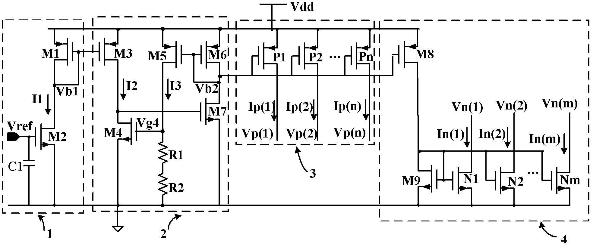
[0021] The stable bias current generating circuit 2 includes PMOS transistors M3, M5 and M6, NMOS transistors M4, M7 and resistors R1 and R2, the sources of the PMOS transistors M3, M5 and M6 are connected to the power supply Vdd, and the gate of the PMOS transistor M3 is connected to The first bias voltage Vb1 in the voltage-current conversion circuit 1, the drains of the PMOS transistor M3 and the NMOS transistor M4 are connected to the gate of the NMOS transistor M7, the sources of the PMOS transistor M4 and the NMOS transistor M7 are connected to the common ground, and the NMOS The gate of the transistor M4 and the drain of the PMOS transistor M5 are jointly connected to one end of the resistor R1, the other end of the R1 is connected in series with the resistor R2 and then connected to the common ground, and the gate and the drain of the PMOS transistor M5 and the gate and the drain of the M6 ​​are connected to the first The second bias voltage Vb2 is connected to the drai...


PUM


Abstract

The invention relates to a sink current and source current generating circuit, which comprises a voltage-current conversion circuit, a stable bias current generating circuit, a source current output circuit and a sink current output circuit. The voltage-current conversion circuit is used for converting reference voltage Vref into current I1 to produce first bias voltage Vb1; the stable bias current generating circuit is used for obtaining high-stability bias current to produce second bias voltage Vb2; the source current output circuit is an output branch used for producing PMOS (P-channel metal oxide semiconductor) source current based on the principle of a PMOS tube current mirror; and the sink current output circuit is an output branch used for producing NMOS (N-channel metal oxide semiconductor) sink current based on the principle of an NMOS tube current mirror. The reference voltage Vref in the system can be directly adopted, the characteristics of high precision and low temperature drift of Vref can be utilized, the bias current of the same high precision and low temperature drift can be obtained, and the problems of high requirements for the precision and temperature coefficient of the bias current in certain circuits can be solved.

Description

technical field [0001] The invention relates to a bias current source, in particular to a generating circuit for sinking and pulling current, which is a bias current source with a low temperature coefficient, and can obtain an output current value with a small temperature coefficient during operation. Background technique [0002] In various integrated circuit systems on a chip, such as power management chips, digital-to-analog / analog-to-digital converters, etc., the bias current source provides appropriate bias for each analog module of the system and becomes an indispensable part of the system. Based on the requirements of on-chip applications, the reference current source should not change with changes in temperature, voltage and various process parameters. Since the current large-scale circuits generally use CMOS technology, in order to realize system integration, the current source based on CMOS technology has become a core module of the whole circuit. Most of the ex...

Claims


Application Information

Patent Timeline
IPC IPC(8): G05F3/16
Inventor 夏晓娟方玉明陈德媛郭宇锋
Owner NANJING UNIV OF POSTS & TELECOMM
Features
  • R&D
  • Intellectual Property
  • Life Sciences
  • Materials
  • Tech Scout
  • Unparalleled Data Quality
  • Higher Quality Content
  • 60% Fewer Hallucinations
Learn More