Broadband anti-metal radio-frequency identification tag and special mounting structure for metal surface thereof

A radio frequency identification tag, metal surface technology, applied to record carriers, instruments, computer parts and other directions used in machines, can solve the problems of tag operating frequency drift, inability to read, limited thickness, etc., to achieve good installation and use stability, The effect of improving broadband characteristics and prolonging operating life

Inactive Publication Date: 2012-06-27
SHANGHAI UNIV
View PDF3 Cites 16 Cited by
  • Summary
  • Abstract
  • Description
  • Claims
  • Application Information

AI Technical Summary

Problems solved by technology

This results in the narrow bandwidth of most tags, unable to adapt to wideband work
Or cause the drift of the working frequency of the tag, resulting in a sharp decrease in the reading distance or even failure to read
[0005] The usual solution is to add a layer of absorbing material between the tag and the metal body. However, due to the limited thickness and the characteristics of the absorbing material itself, the radiation efficiency of the tag antenna will decrease, and the same tag cannot be obtained. Stable reading performance on common object surfaces
In addition, the usual UHF band tags with broadband characteristics are large in size and unsatisfactory in selectivity, so they are not suitable for management applications of small metal tools

Method used


Image

  • Broadband anti-metal radio-frequency identification tag and special mounting structure for metal surface thereof
  • Broadband anti-metal radio-frequency identification tag and special mounting structure for metal surface thereof
  • Broadband anti-metal radio-frequency identification tag and special mounting structure for metal surface thereof

Examples


Embodiment 1

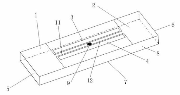
[0033] see figure 1 , a broadband anti-metal radio frequency identification tag, the front of the label substrate 8 is provided with a label patch antenna and a chip 9, and the back of the label substrate 8 is provided with a grounding plane 7, and the entire radio frequency identification tag can be fixed on the metal surface. On the working surface of the entire radio frequency identification tag, the patch antenna is arranged symmetrically with the chip 9 as the center, and the patch antenna includes a patch antenna body and a coupling antenna unit fixed on the front of the label substrate 8, and the patch antenna body includes two parts, They are respectively the first part 1 and the second part 2 which are located near the two ends of the label substrate 8 in the longitudinal direction. The two parts of the patch antenna body are electrically connected to the chip 9 through the first feeder 11 and the second feeder 12 respectively. A planar empty area is formed between th...

Embodiment 2

[0041] The technical solution of this embodiment is basically the same as that of Embodiment 1, the difference is that:

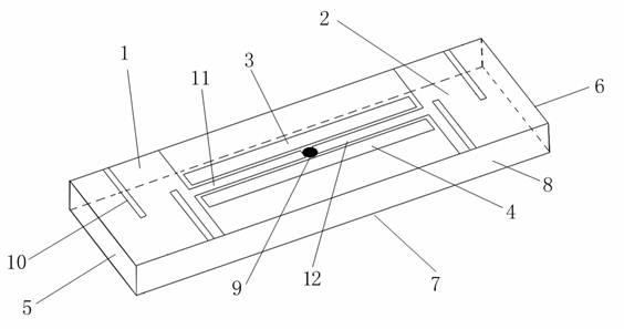
[0042] see figure 2 , in this embodiment, the first part 1 and the second part 2 include a slotted structure 10, and the number of slots in the slotted structure 10 is less than six. In this embodiment, through the adjustment of the slotted structure 10, the electromagnetic characteristics of the antenna body can be effectively improved. The electromagnetic characteristics of the patch antenna are related to the antenna impedance. The electromagnetic characteristics of a general uniform impedance antenna mainly depend on the electrical length of the antenna. Therefore, the radio frequency identification tag of the present invention has an additional degree of freedom to adjust the electromagnetic characteristics of the antenna body, thereby making the design of the radio frequency identification tag of the present invention more flexible.

[0043] In the ...

Embodiment 3

[0046] The technical solution of this embodiment is basically the same as that of Embodiment 1, the difference is that:

[0047] see Figure 4 , a metal surface special installation structure for broadband anti-metal radio frequency identification tags, forming a metal surface recessed structure space 102 for accommodating metal radio frequency identification tags 101 on the metal surface, and the radio frequency identification tag 101 is built and fixed in the metal surface recessed structure space 102 in. The entire radio frequency identification tag 101 can be directly fixed on the metal surface by double-sided adhesive tape, adhesive, etc., or can be embedded in the inner depression of the metal surface by a fixing material or a special installation structure. In this embodiment, the radio frequency identification tag 101 is directly fixed and installed on the surface of the metal, and can be directly embedded in the recessed structure space 102 of the metal surface. The ...


PUM


Abstract

The invention discloses a broadband anti-metal radio-frequency identification tag and a special mounting structure for a metal surface thereof. The front face of a tag substrate is provided with a tag patch antenna and a chip, the patch antenna comprises a first part and a second part, the first part and the second part are respectively and electrically connected with the chip through a first feed line and a second feed line, the vertical surfaces at two ends of the tag substrate are respectively and symmetrically provided with a first short circuit wall and a second short circuit wall, and a first coupling line unit and a second coupling line unit are symmetrically arranged near the two ends of the first feed line and the second feed line, so that a capacitive coupling structure is formed between the antenna body and a coupling antenna unit. In the special mounting structure for the metal surface, a depressed structural space for accommodating the tag is formed on the metal surface, and the tag is fixedly arranged in the depressed structural space of the metal surface. While the wave absorbing material needs not to be increased additionally, the reading and writing performance like adhesion to the surface of an ordinary object can be realized. Moreover, the radio-frequency identification tag has large bandwidth and a small size.

Description

technical field [0001] The invention relates to an RFID (Radio Frequency Identification, radio frequency identification) tag, in particular to a radio frequency identification tag which can be integrated with a metal body and used in combination with a metal surface and a special installation structure for the metal surface. Background technique [0002] RFID technology is a non-contact radio frequency identification technology. In RFID technology, the required information is stored in tags including IC (Integrated Circuit, integrated circuit) chips and antennas for wireless communication; and the RFID reader capable of collecting tag information is in LF (Low Frequency, low frequency), UHF (Ultra High Frequency, ultra-high frequency), RF (Radio Frequency, radio frequency), MWF (Microwave Frequency, microwave frequency band) frequency bands communicate with tags. [0003] Due to the different radio regulations of various countries, the working frequency bands of UHF Passive...

Claims


Application Information

Patent Timeline
Patent Type & Authority Applications(China)
IPC IPC(8): G06K19/077
Inventor 龙平叶明操瑞鑫
Owner SHANGHAI UNIV
Why Eureka
Try Eureka