
Distributed image high power tube core

A high-power, decentralized technology, applied in the direction of improving amplifiers to improve efficiency, electrical components, electrical solid-state devices, etc., can solve problems such as increased circuit complexity, single chip output power limitation, and reduced efficiency, to improve uniform heat dissipation performance, avoiding local hot spots, and good electrical properties

Inactive Publication Date: 2012-06-27
NO 55 INST CHINA ELECTRONIC SCI & TECHNOLOGYGROUP CO LTD
View PDF3 Cites 3 Cited by
  • Summary
  • Abstract
  • Description
  • Claims
  • Application Information

AI Technical Summary

Problems solved by technology

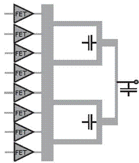
For practical application, the longitudinal size of the chip cannot be larger than half the wavelength, so the output power of a single chip is limited
In order to meet the output power requirements, it is often necessary to synthesize multiple chips, which increases the overall size, reduces efficiency, and increases circuit complexity. At the same time, after the single-column gate width is increased, the heat source in the middle of the device is relatively concentrated, which affects the reliability of the chip.

Method used


Image

  • Distributed image high power tube core
  • Distributed image high power tube core
  • Distributed image high power tube core

Examples


Embodiment 1

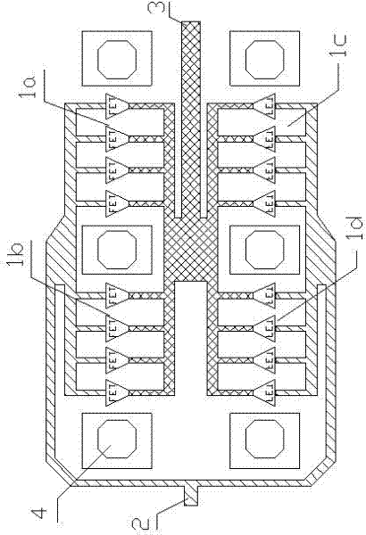
[0025] image 3 It is an eight-way synthesis design of dual rank dies according to the embodiment of the present invention. Among them, 1a, 1b, 1c, and 1d are HEMT unit cells, and each unit cell contains 6 FETs; each unit cell is isolated by the source bar through hole 4, and the heat source is evenly separated while the HEMT source is grounded. , to avoid excessive concentration of heat in the middle. HEMT unit cells 1a and 1b are arranged in the same direction, HEMT unit cells 1c and 1d are arranged in the same direction, HEMT unit cells 1a and 1c are mirror-symmetrically distributed, and HEMT unit cells 1b and 1d are mirror-symmetrically distributed. At the same time, the HEMT unit cells 1a, 1b, 1c, and 1d as a whole and the HEMT unit cells 1a', 1b', 1c', and 1d' are mirror-symmetrically distributed on the basis of the center line in the figure. 2 in the figure is the microwave signal input power distribution network, which evenly distributes the microwave signal to each ...

Embodiment 2

[0027] Figure 5 It is an eight-way synthesis design of four columns of dies in the embodiment of the present invention. This embodiment adopts a four-column die layout design, which reduces the vertical size of the chip by half under the premise of the same gate width; the same vertical size of the chip can double the total gate width and greatly increase the output power of a single chip. 1a-1h in the figure are HEMT unit cells. HEMT unit cells 1a~1d are arranged in the same direction, HEMT unit cells 1e~1h are arranged in the same direction, HEMT unit cell 1a and HEMT unit cell 1e are mirror images of each other, HEMT unit cell 1b and HEMT unit cell 1f are mirror images of each other The HEMT unit cell 1c and the HEMT unit cell 1g are in a mirror image relationship with each other, and the HEMT unit cell 1d and the HEMT unit cell 1h are in a mirror image relationship with each other. 2 in the figure is the input power distribution network, which evenly distributes the mic...


PUM


Abstract

The invention relates to a distributed image high power tube core, which comprises a substrate, high electron mobility transistor (HEMT) unit cells 1a, 1b, 1c and 1d, a power distribution network, a power synthesis network and a source strip grounding radiating through hole, wherein the HEMT unit cells 1a, 1b, 1c and 1d, the power distribution network, the power synthesis network and the source strip grounding radiating through hole are all arranged on the substrate, and source electrodes of the HEMT unit cells 1a, 1b, 1c and 1d are connected with the ground through the source strip grounding radiating through hole. The HEMT unit cells 1a, 1b, 1c and 1d are distributed on the substrate evenly and are further distributed and separated by adopting the source strip grounding through hole. The HEMT unit cell source electrodes are grounded well through the source strip grounding radiating through hole, good electric performance is achieved, and the tube core is separated evenly in the longitudinal direction by using the size of a power distribution / synthesis network simultaneously, therefore even distribution of heating sources is achieved, local hot spots are avoided, radiating uniformity of the tube core is greatly improved, and stability of devices under high power is guaranteed.

Description

technical field [0001] The invention relates to a high-power tube core, specifically, a high-power tube core with a distributed mirror image. Background technique [0002] Solid-state microwave power devices and monolithic circuits are core components in systems such as electronic countermeasures, phased array radar, precision strikes, microwave communications, and satellite aerospace. Due to the particularity of their application background, solid-state microwave power devices and monolithic circuits have always been It is a key field for foreign countries to impose technology blockade and product embargo on my country; and solid-state power amplifier chips, as the core components, are subject to stricter control. At present, the high-performance solid-state microwave power monolithic chips working in the C-band and above frequency bands are mainly GaAs-based second-generation semiconductor devices. As the main representative of the third-generation semiconductors, GaN mate...

Claims


Application Information

Patent Timeline
IPC IPC(8): H01L23/367H01L27/02H03F1/02
Inventor 张斌余旭明陈堂胜任春江黄念宁
Owner NO 55 INST CHINA ELECTRONIC SCI & TECHNOLOGYGROUP CO LTD
Learn More