


Quick Research
Generate reliable direction feasibility study reports for your R&D in just a few steps.

Technical Q&A
Discover and master advanced knowledge NOW. Basics, ideas, possibilities, all at once.

Find Solutions
As an expert in R&D theories, this can generate solutions to your technical problems instantly.

Evaluate Feasibility
Analyze your overall solution with one click, know your potential R&D risks in advance.

Monitor Landscape
Get weekly tech updates, stay abreast of the latest tech innovations and key insights.
Measuring apparatus
A measuring device and probe technology, applied in diagnostic recording/measurement, medical science, diagnosis, etc., can solve the problems of reconstructed images including artifacts, limited sound wave directionality, etc.
- Summary
- Abstract
- Description
- Claims
- Application Information
AI Technical Summary
Problems solved by technology
Method used
Image

Examples
Embodiment 1
[0036] Embodiment 1 of the present invention will be described below.
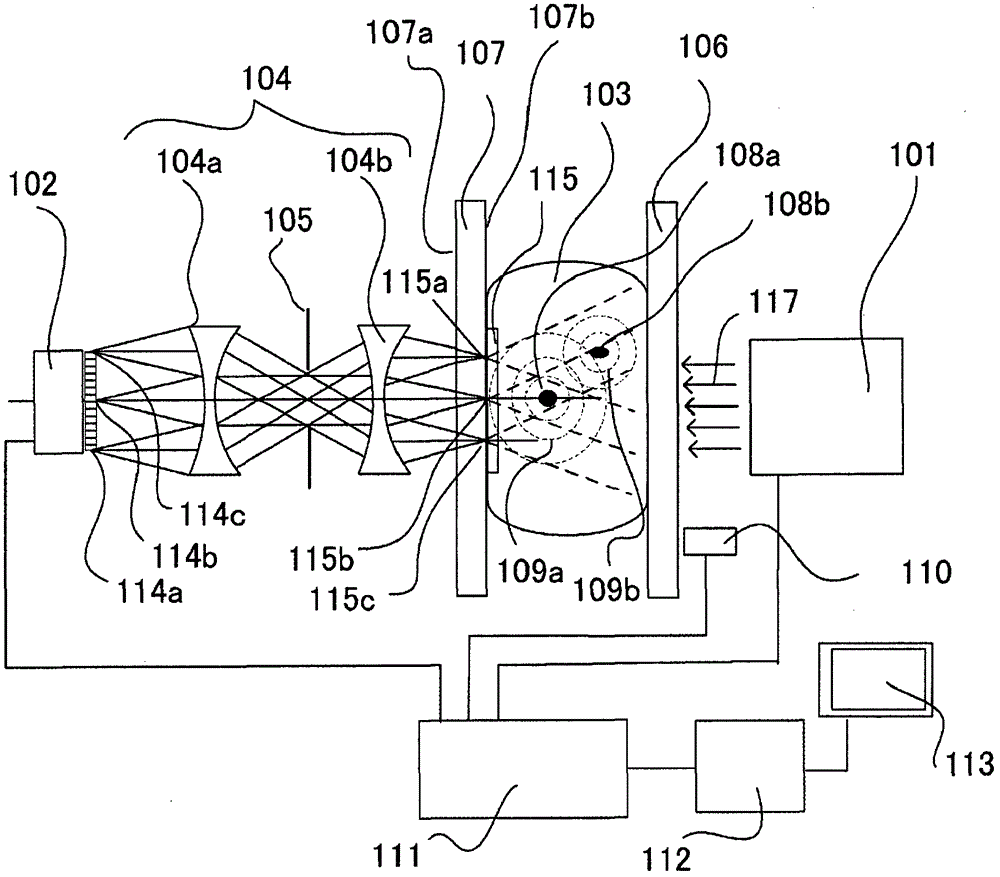
[0037] figure 1 is a schematic diagram showing the configuration of Embodiment 1 according to the present invention. The object measurement device described in this embodiment is a living body measurement device using photoacoustic tomography, which is a technique for reconstructing an image from a reception signal of an acoustic wave generated inside a subject by pulse irradiation of laser light .
[0038] Assume that the object in this embodiment is a human breast. The device performs imaging of blood vessels inside the breast using photoacoustic tomography.
[0039] exist figure 1 Here, the irradiation optical system 101 irradiates the subject 103 with light from a pulsed light source (not shown) that oscillates wavelengths in the near-infrared region with a predetermined light energy density distribution. The object 103 is held between two object holding plates 106 and 107 . The object holding pl...
Embodiment 2
[0066] Embodiment 2 of the present invention will be described below.
[0067] The object measuring device described in this embodiment is basically a living body measuring device using photoacoustic tomography similarly to Embodiment 1. Here, however, the illumination optics and probe are configured to be movable so that the object can be scanned, whereby images of a wider field of view can be produced.
[0068] Figure 5 is a schematic diagram showing the configuration of Embodiment 2 according to the present invention. The living body measuring device of this embodiment uses photoacoustic tomography technology to obtain information inside the object. That is, the device of the present embodiment receives acoustic waves generated inside the object by pulse irradiation of laser light, and reconstructs the received signal to obtain an image of the spatial distribution of absorption coefficient corresponding to the wavelength of the irradiated laser light.
[0069] Assume th...
Embodiment 3
[0092] Embodiment 3 of the present invention will be described below. Figure 8 is a diagram showing an outline of a main part of an apparatus according to Embodiment 3. The same number is given with the Figure 5 Components with the same functions as those of the device, and these same numbers will not be described again. The device of the present embodiment has a configuration in which a probe-side illuminating optical system 229 and a photodetector 228 are provided inside the probe-side bracket 222 of the device according to Embodiment 2. Similar to Embodiment 2, the device of this embodiment is a device for obtaining a reconstructed image based on the principle of photoacoustic tomography.
[0093] The device of the present embodiment irradiates the subject 203 with the irradiation light 227 from the irradiation optical system 229, and the photodetector 228 captures the timing of the light irradiation.
[0094] Arranging the illumination optical system 229 inside the pr...
PUM
 Abstract
Description
Claims
Application Information
 - R&D Engineer
- R&D Manager
- IP Professional
- Industry Leading Data Capabilities
- Powerful AI technology
- Patent DNA Extraction
Browse by: Latest US Patents, China's latest patents, Technical Efficacy Thesaurus, Application Domain, Technology Topic, Popular Technical Reports.
© 2024 PatSnap. All rights reserved.Legal|Privacy policy|Modern Slavery Act Transparency Statement|Sitemap|About US| Contact US: help@patsnap.com