High-current baffleless magnesium electrolytic tank

A magnesium electrolytic cell without separator technology, which is applied in the field of magnesium electrolysis, can solve the problems of research and development lag, poor sealing, serious corrosion, etc., and achieve obvious energy saving effects and lower tank pressure

Active Publication Date: 2012-07-04
EAST CHINA UNIV OF SCI & TECH
View PDF4 Cites 3 Cited by
  • Summary
  • Abstract
  • Description
  • Claims
  • Application Information

AI Technical Summary

Problems solved by technology

The current efficiency of the 120kA magnesium electrolyzer without separators currently in operation in my country is about 76-78%. The power consumption of the instrument is large, the sealing is poor, the pollution is serious, and the corrosion is serious, the life is short, and the cost is high. The entire magnesium electrolysis industry is far behind foreign countries. huge
Due to the absence of industry demand traction, my country's technology research and development is also seriously lagging behind foreign countries. At present, it is difficult to design a magnesium electrolyzer with a current intensity higher than 160kA in China.

Method used


Image

  • High-current baffleless magnesium electrolytic tank
  • High-current baffleless magnesium electrolytic tank
  • High-current baffleless magnesium electrolytic tank

Examples


Embodiment 1

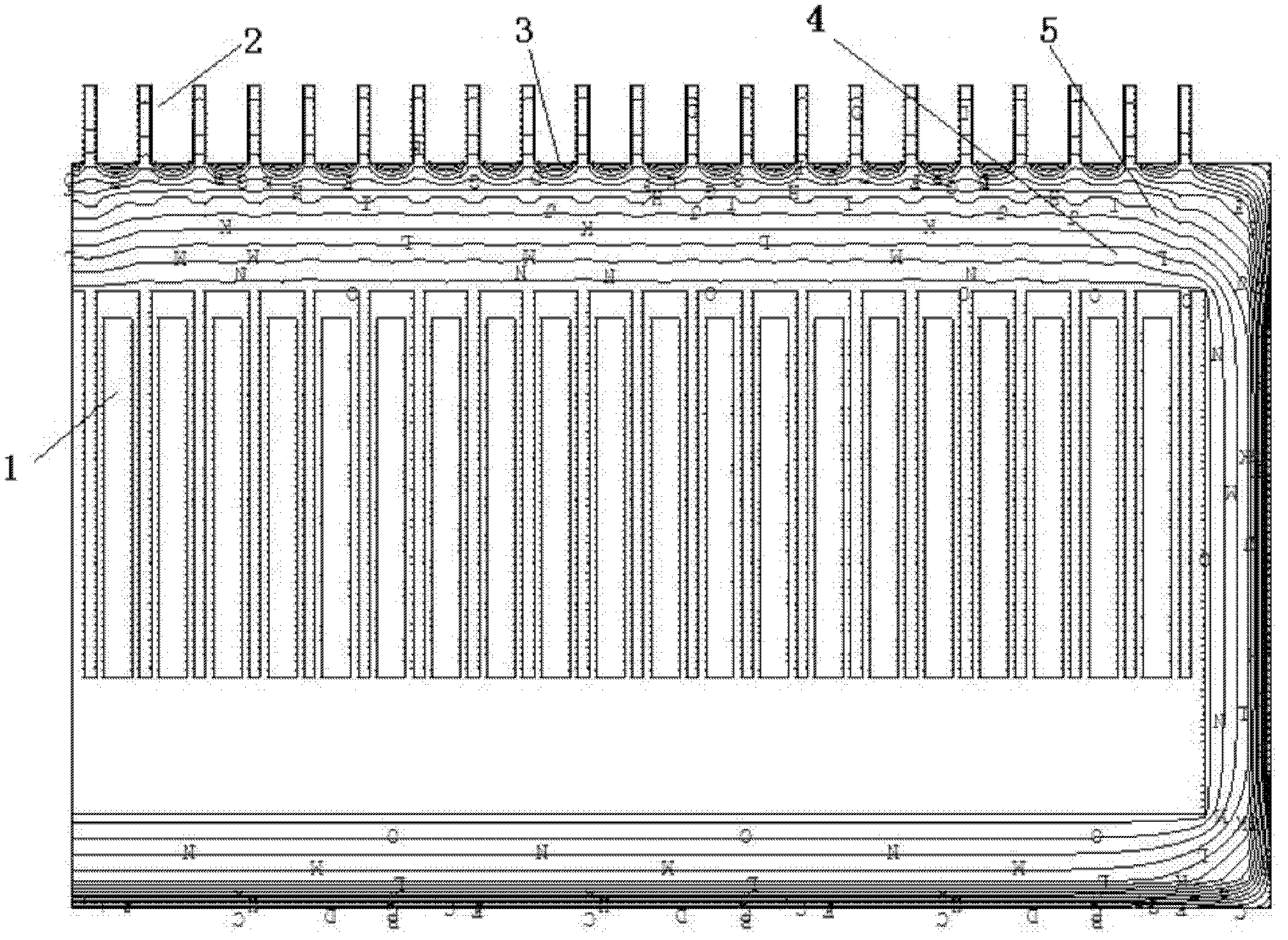
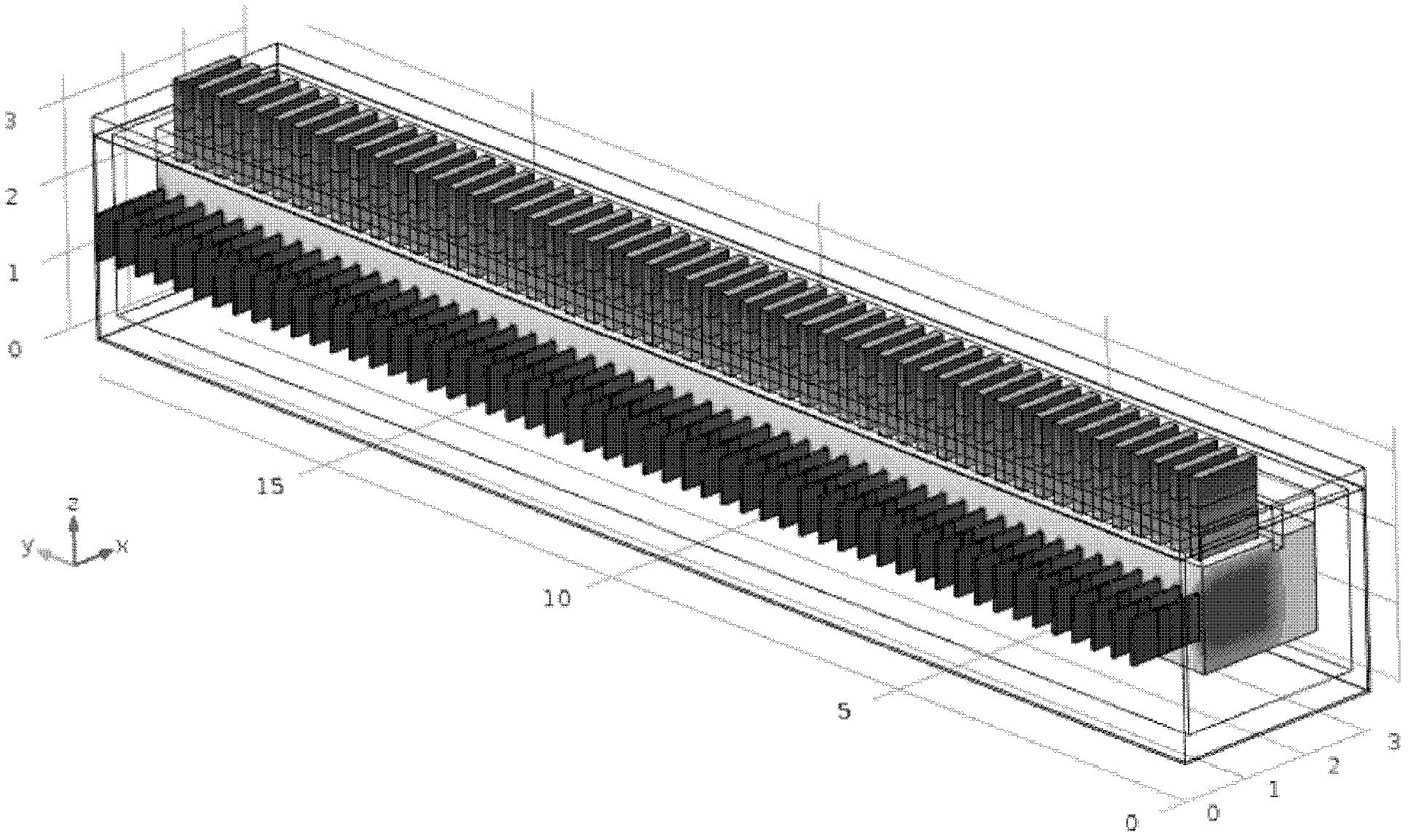
[0022] See attached Figure 1-3 , This kind of high-current magnesium electrolytic cell without separators, its basic components are anode 1, cathode 2, tank shell 3, refractory layer 4, insulation layer 5. After optimizing the electric field, thermal field and flow field, a separatorless magnesium electrolytic cell with a current intensity of 300kA was designed. The current efficiency of the electrolytic cell can reach 90% by calculation. The total length of the electrolytic cell is 12.7 meters. A total of 40 anodes and 41 cathodes are designed. The design current intensity is 300kA, the electrolysis design temperature is 700℃, the anode and cathode distance of the electrolytic cell is 0.04 meters, the cathode is 0.5m longer than the anode in the depth direction of the electrolytic cell, 0.1m longer in the direction of the magnesium chamber, and the electrolyte level is away from the cathode. The top is 0.2m, and the overall cell pressure drop is 4.5 volts. The temperature dis...

Embodiment 2

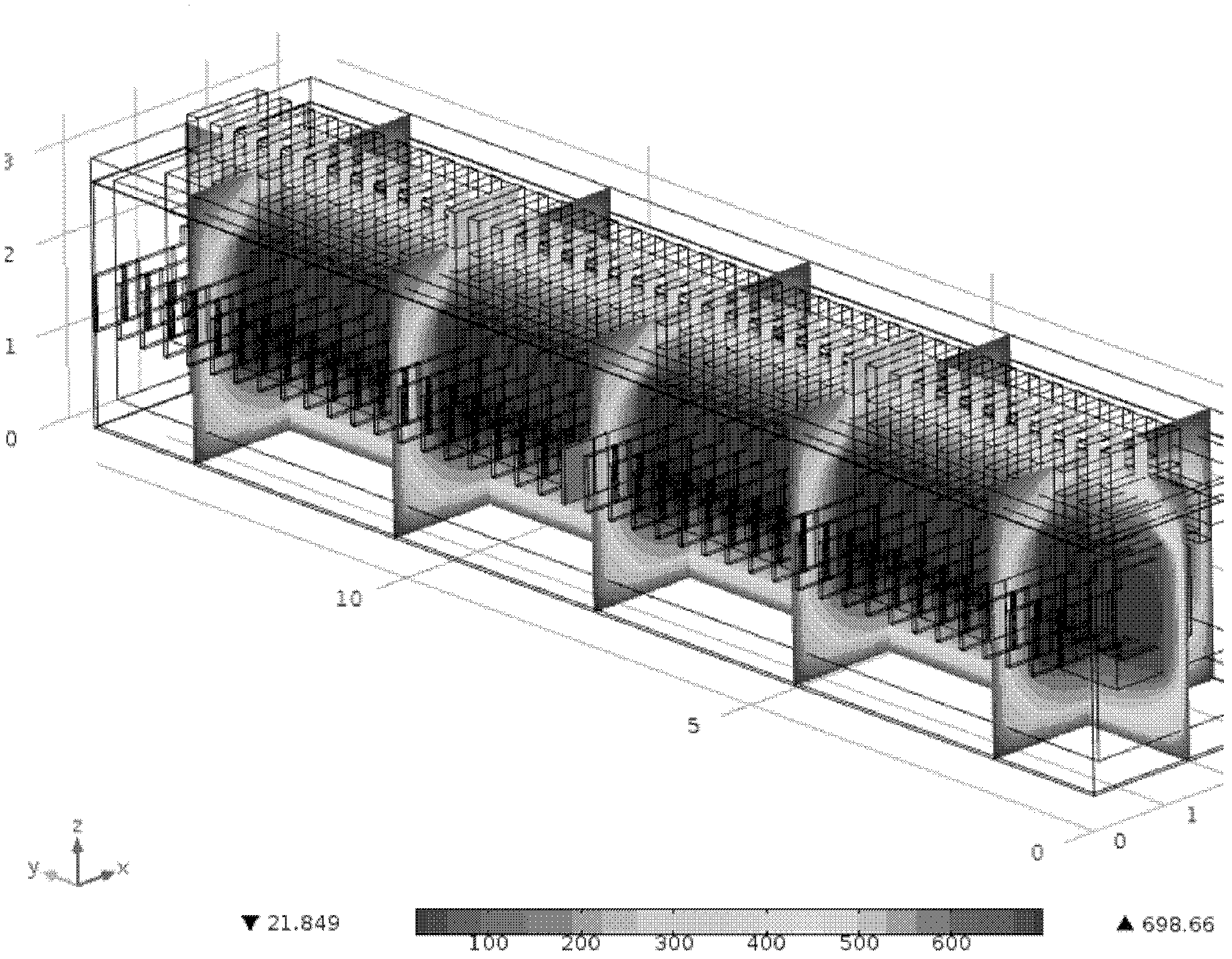
[0025] After optimizing the electric field, thermal field, and flow field, a separatorless magnesium electrolytic cell with a current intensity of 400kA was designed. The current efficiency of the electrolytic cell can reach 93% by calculation. A total of 54 anodes and 55 cathodes are designed, and the design current intensity is 400kA. The electrolysis design temperature is 700℃, the cathode and anode distance of the electrolytic cell is 0.04m, the cathode is 0.4m longer than the anode in the depth direction of the electrolysis cell, 0.2m longer in the direction of the magnesium chamber, and the electrolyte level is 0.3m from the top of the cathode. The voltage drop is 5V, and the voltage distribution of the electrolytic cell is calculated as image 3 :

[0026] by image 3 It can be seen that in the electrolytic cell, the anode head has the highest voltage because it is a voltage input, which is 5V, which is shown in red in the figure. The current flows out of the electrolytic ...


PUM

PropertyMeasurementUnit
current efficiencyaaaaaaaaaa

Abstract

The invention relates to a high-current baffleless magnesium electrolytic tank. The relative positions of the cathode and the anode and the height of an electrolyte liquid surface of the high-current baffleless magnesium electrolytic tank are optimized, the electric field, the thermal field, the magnetic field and the flow field of the interior of the 300-400 kA high-current magnesium electrolytic tank are analyzed by using numerical calculation, and the tank voltage of the baffleless magnesium electrolytic tank can be effectively lowered through optimizing the relative positions and the sizes of the cathode and the anode. Compared with the domestic prior art, the optimized electrolytic tank has the advantages that the tank voltage of the optimized electrolytic tank can be lowered by about 0.1 V, and the energy-saving effect of the magnesium electrolytic tank is very obvious when the current is in the range of 300 to 400 kA.

Description

【Technical Field】 [0001] The invention relates to the technical field of magnesium electrolysis, and specifically, is a design of a large-current magnesium electrolytic cell without a separator. 【Background technique】 [0002] Magnesium is an extremely important non-ferrous metal that can form a variety of high-strength magnesium alloys with other metals. Magnesium alloy has the advantages of light specific gravity, high specific strength and specific rigidity, good thermal conductivity, good damping, shock absorption and electromagnetic shielding performance, easy processing and forming, and easy recycling. It is known as the "21st Century Green Engineering Material". [0003] Magnesium alloy has many excellent mechanical properties. With the development of the magnesium smelting industry, it has expanded from the field of national defense to people's daily life, such as automobiles, home appliances, mobile phones, computers, communications, etc., to meet the requirements of light...

Claims


Application Information

Patent Timeline
Patent Type & Authority Applications(China)
IPC IPC(8): C25C7/00C25C3/04
Inventor 孙泽路贵民宋兴福汪瑾刘程琳于建国
Owner EAST CHINA UNIV OF SCI & TECH
Why Eureka
Try Eureka