Digital-shaft angle signal converting method
A signal conversion and digital signal technology, applied in the direction of digital-to-analog converter, transmission of sensing components using electromagnetic/magnetic devices, etc., can solve the problems of low cost performance, single function, unfavorable angle measurement and application in the field of control, etc. The effect of strong scalability and high conversion accuracy
- Summary
- Abstract
- Description
- Claims
- Application Information
AI Technical Summary
Problems solved by technology
Method used
Image
Examples
Embodiment example 1
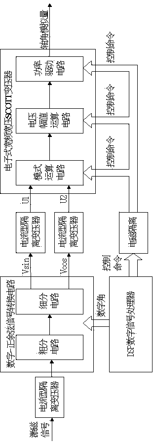
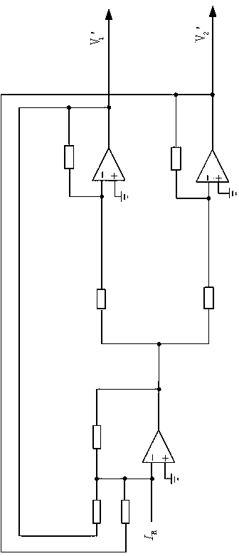
[0024] Implementation case 1, refer to Figure 1-4 , a digital-axis angle signal conversion method, the circuit for realizing the method includes a digital-sincosine signal conversion circuit, an electronic wide-bandwidth wide-voltage SCOTT transformer and a DSP digital signal processor;
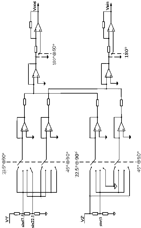
[0025] The digital-sincosine signal conversion circuit is composed of a subdivision circuit and a rough division circuit; the subdivision circuit is a low 16-bit weight resistance network D / A conversion circuit, and the rough division circuit is composed of a precision resistance network, a precision operational amplifier and an analog switch; The electronic wide-band wide-voltage SCOTT transformer is composed of a mode operation circuit, a voltage amplitude operation circuit and a power drive circuit;
[0026] The digital-sincosine signal conversion circuit receives the external input excitation signal isolated by the current-type transformer and the 20-bit digital angle θ sent by the DSP d...
Embodiment 2
[0027] Embodiment 2, in the digital-axis angle signal conversion method described in Embodiment 1: the digital-sin-cosine signal conversion circuit is realized by a high 4-bit coarse weighted resistance network and a low 16-bit subdivision weighted resistance network, and the weighted resistance network is equal to Adopt low-temperature drift precision resistance network architecture, high 4-bit rough angle and low 16-bit subdivision angle are synthesized into 20-bit full angle according to trigonometric function positive and cosine angle sum and difference digital expression; realize 0.001° precision 2V low voltage positive Cosine signal output.
Embodiment 3
[0028] Embodiment 3, in the digital-axis angle signal conversion method described in Embodiment 1: the mode operation circuit is composed of a precision resistor, a precision operational amplifier and a front-end input relay, and receives two fixed sine and cosine signals: According to different output signal modes, switch the corresponding circuit; when the four-wire resolver signal is output, the SGND, cosθ, sinθ and CGND signals are amplified and then output to the voltage amplitude calculation circuit; when the three-wire auto-synchronizer signal is output, SGND , -sin(θ+240°) and sinθ signals are amplified and output to the voltage amplitude operation circuit.
PUM
 Abstract
Description
Claims
Application Information
 - R&D
- Intellectual Property
- Life Sciences
- Materials
- Tech Scout
- Unparalleled Data Quality
- Higher Quality Content
- 60% Fewer Hallucinations
Browse by: Latest US Patents, China's latest patents, Technical Efficacy Thesaurus, Application Domain, Technology Topic, Popular Technical Reports.
© 2025 PatSnap. All rights reserved.Legal|Privacy policy|Modern Slavery Act Transparency Statement|Sitemap|About US| Contact US: help@patsnap.com


