
Magnetic core

A magnetic core and toroidal core technology, applied in the field of magnetic integration, can solve the problems of complex production and assembly processes, loss of the inherent function of the magnetic core, and further rise, and achieve the effects of simple structure, easy processing and prolonging service life.

Active Publication Date: 2012-07-04
MORNSUN GUANGZHOU SCI & TECH
View PDF10 Cites 6 Cited by
  • Summary
  • Abstract
  • Description
  • Claims
  • Application Information

AI Technical Summary

Problems solved by technology

[0008] 2. The production and assembly process is relatively complicated
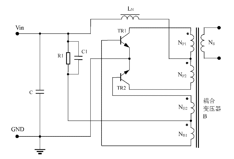
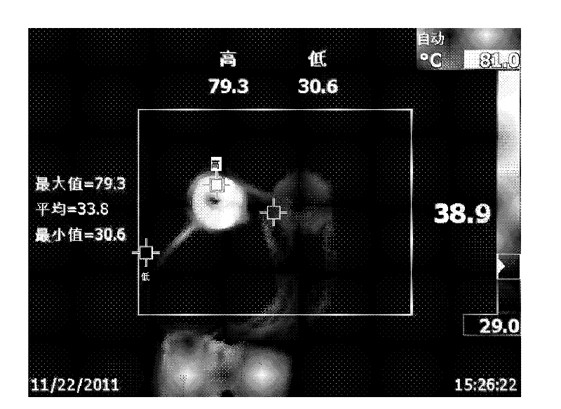
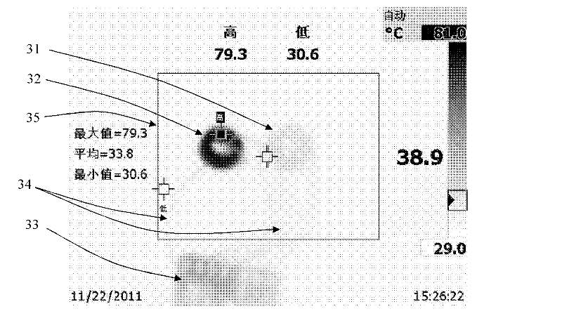
from figure 2 , image 3 It can be seen that the inductance L N The magnetic core with the same size as the power transformer B is used, and both have such a high temperature. If the inductance L is reduced N When the output is short-circuited, the temperature of the inductor LN will rise further, even exceeding 150 degrees, and the magnetic core will approach or exceed its own Curie temperature point, causing demagnetization and losing the inherent function of the magnetic core

Method used


Image

  • Magnetic core
  • Magnetic core
  • Magnetic core

Examples


Embodiment Construction

[0047] Figure 4 It is a perspective view of the first embodiment of the present invention. Below to Figure 4 Taking the first embodiment as an example, it shows that the transformer or the common mode inductor and the magnetic flux line between the inductor are independent, Figure 6 for Figure 4 Arrow 61 is a schematic diagram of the diameter of the magnetic ring. Arrow 61 extends out of the magnetic material along the direction of arrow 62. Along the diameter direction of the annular magnetic core, a cylindrical magnetic column of the same material extends outward from the outer surface of the closed magnetic core with no air gap magnetic circuit. , to achieve Figure 4 The first embodiment of . Winding a coil on a magnetic core can realize an integrated device of a transformer and an inductor, see Figure 7 , wherein, 71 is a winding of the transformer, 72 is another winding of the transformer, and 73 is an inductor; Figure 7 It is also possible to realize the int...


PUM


Abstract

The invention discloses a magnetic core which comprises an air-gap-free closed-magnetic-circuit magnetic core, wherein the external surface of the air-gap-free closed-magnetic-circuit magnetic core is provided with one or more than one same-material cylindrical magnetic column extending outwards; the air-gap-free closed-magnetic-circuit magnetic core is an annular magnetic core, and the cylindrical magnetic column extends outwards along the diameter direction of the annular magnetic core; alternatively, the air-gap-free closed-magnetic-circuit magnetic core is an annular magnetic core, and the cylindrical magnetic column extends outwards along the direction perpendicular to the diameter direction of the annular magnetic core. The magnetic core can be applicable to a self-excited push-pull type transformer with output short circuit protection function, so that magnetic lines of force between the transformer or a common-mode inductor and an inductor are independent and are not mutually influenced; magnets of the same material are magnetically integrated, and the magnetic core is formed through one set of moulds and is easy to machine during production, and the product has high conformance; and the magnetic core is integrally manufactured by using the same mould and has good heat transfer effect.

Description

technical field [0001] The invention relates to the field of magnetic integration technology, in particular to a magnetic core used in a power converter. Background technique [0002] Existing power converters, in order to pursue higher power density, that is, under the same volume, power converters can achieve greater output power, have begun to develop towards magnetic integration; on the other hand, in order to achieve good electromagnetic compatibility , Magnetic integration technology has also begun to be used for common mode inductors and differential mode inductors to reduce the volume. Common mode Choke (Common mode Choke), also known as common mode choke coil, is also called conjugate inductor in some documents, and is often used to filter common mode electromagnetic interference signals in switching power supplies. In fact, common mode inductors are just a form of transformer. In its most basic form, a transformer consists of two sets of coils wound with wire and...

Claims


Application Information

Patent Timeline
IPC IPC(8): H01F27/24H01F41/02H01F27/30
Inventor 王保均
Owner MORNSUN GUANGZHOU SCI & TECH
Learn More