Highly efficiently luminescent electroluminescent device

An electroluminescent device, high-efficiency technology, applied in the direction of electro-solid devices, electrical components, semiconductor devices, etc., can solve the problems of equipment short circuit, complex, unable to effectively increase the output of light, etc., to improve the efficiency of light output and reduce production. cost effect

Active Publication Date: 2012-07-04
江苏壹光科技有限公司
View PDF11 Cites 24 Cited by
  • Summary
  • Abstract
  • Description
  • Claims
  • Application Information

AI Technical Summary

Problems solved by technology

[0007] In most cases, these light-enhancing structures are placed on the outer surface of the transparent substrate. Since organic light can never reach these structures, these light-enhancing structures can only use air light and substrate light.
Since organic light accounts for half of the emitted light, these light-enhancing structures cannot effectively increase the output of light. In order to effectively extract these three kinds of light, the light-enhancing structure must be located near the transparent electrode. The bottom emission structure in the existing invention, Setting the light-enhancing struc

Method used


Image

  • Highly efficiently luminescent electroluminescent device
  • Highly efficiently luminescent electroluminescent device
  • Highly efficiently luminescent electroluminescent device

Examples


Embodiment 1

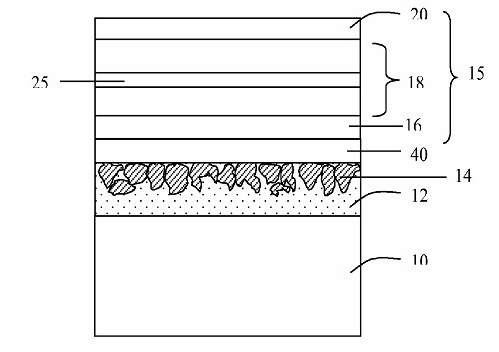
[0081] like figure 1 As shown, the electroluminescent device of this embodiment includes a transparent substrate 10, a light-enhancing structure, and an LED unit 15. The LED unit 15 includes a transparent electrode layer 16, a light-emitting element 18 with a light-emitting layer 25, and a reflective electrode layer 20. The structure includes a light scattering layer 14 with a layer of high refractive index particles, a surface smoothing layer 40 with a high refractive index, and a protective layer 12 .

Embodiment 2

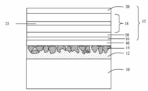
[0083] like figure 2 As shown, the electroluminescent device of this embodiment includes a transparent substrate 10, a light-enhancing structure, and an LED unit 15. The LED unit 15 includes a transparent electrode layer 16, an anti-short-circuit layer 50, a light-emitting element 18 with a light-emitting layer 25, and a reflection The electrode layer 20 has a light-enhancing structure including a light-scattering layer 14 with a layer of high-refractive-index particles, a surface-smoothing layer 40 with a high-refractive index, and a protective layer 12 .

Embodiment 3

[0085] like image 3 As shown, the electroluminescent device of this embodiment includes a transparent substrate 10, a light-enhancing structure and an LED unit 15. The LED unit 15 includes a transparent electrode layer 16, an anti-short-circuit layer 50, a light-emitting element 18 with a light-emitting layer 25, a connection The unit 70, the light emitting element 18a with a light emitting layer 25a and the reflective electrode layer 20, the light enhancement structure includes a light scattering layer 14 with a layer of high refractive index particles, a surface smoothing layer 40 with a high refractive index and a protective layer 12.

[0086] The connecting units enable electrons of two adjacent organic light-emitting units to be injected into the electron transport layer, and holes to be injected into the hole transport layer. Preferably, the connecting unit is transparent and is connected in series on the OLED. Also preferably, the connection unit does not have much in...


PUM

PropertyMeasurementUnit
Particle sizeaaaaaaaaaa
Thicknessaaaaaaaaaa
Thicknessaaaaaaaaaa

Abstract

The invention provides a highly-efficiently luminescent electroluminescent device. The highly-efficiently luminescent electroluminescent device comprises a transparent base, an intensifier structure and an LED (Light Emitting Diode) unit, wherein the LED unit comprises a transparent electrode, a light emitting component with at least one light emitting layer and a reflecting electrode layer; and the intensifier structure comprises a light scattering layer with a layer of high-refractive-index particles, a surface smoothing layer with high refractive index and a protecting layer, the surface smoothing layer comprises two elements as follows: one element is a high-refractive-index inorganic nanometer particle coated with a small organic molecule, and the other element is a polymerizable monomer or a macromolecular polymer. The highly-efficiently luminescent electroluminescent device disclosed by the invention has the following advantages of: (1) improving light output efficiency; and (2) reducing production cost.

Description

technical field [0001] The invention relates to an electroluminescent device, in particular to an electroluminescent device capable of improving luminous efficiency. Background technique [0002] Electroluminescent devices (LEDs) mainly include the following types: organic electroluminescent devices (OLEDs), polymer electroluminescent devices (PLEDs) and inorganic electroluminescent devices, such as QD-LEDs. [0003] Existing LEDs usually include a transparent substrate, a transparent first electrode layer, a light emitting element and a reflective second electrode layer. When electrons and holes are injected from two electrons through the light-emitting element into the LED, they combine or collide together to generate light. The light-emitting element usually includes several layers of materials, including at least one light-emitting layer for emitting light. A light emitting element of an OLED generally includes an electron injection layer, an electron transport layer, o...

Claims


Application Information

Patent Timeline
IPC IPC(8): H01L33/58H01L51/52H01L51/54H01L51/56H01L33/00
Inventor 王锦山张建新彭军军顾辛艳
Owner 江苏壹光科技有限公司
Why Eureka
Try Eureka