Lubricating varnish for coating a metal component or applied to a metal component

A metal component, coating technology, applied in the field of lubricating paint

Inactive Publication Date: 2012-07-04
SCHAEFFLER TECH AG & CO KG
View PDF7 Cites 21 Cited by
  • Summary
  • Abstract
  • Description
  • Claims
  • Application Information

AI Technical Summary

Problems solved by technology

The disadvantage of the systems described is primarily the limi

Method used


Image

  • Lubricating varnish for coating a metal component or applied to a metal component
  • Lubricating varnish for coating a metal component or applied to a metal component
  • Lubricating varnish for coating a metal component or applied to a metal component

Examples


Embodiment Construction

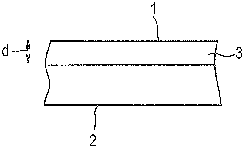
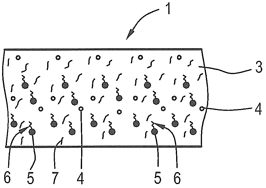
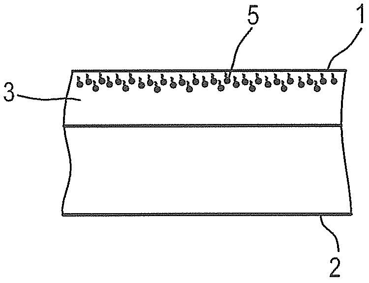
[0089] figure 1 The lubricant varnish 1 according to the invention is shown in the form of a coating on a component 2 , in particular a metal component. Here, the component 2 does not have to have a flat surface, but can also have any shape, for example a curved or angled shape. Furthermore, the component 2 can be three-dimensionally structured on its surface. For example, a certain roughness can be intentionally provided so that the lubricating paint 1 adheres better to the surface of the component 2 . Between the component 2 and the lubricant varnish 1 there is a relatively stable, preferably insoluble composite formed by the matrix 3 of the hardened lubricant varnish 1 . Hardening of the matrix 3 can take place, for example, by heating or UV radiation, NIR radiation, IR radiation or particle radiation. In this embodiment, the layer thickness of the lubricant varnish 1 is approximately 25 μm. The tribological properties of the component 2 are significantly improved by ap...


PUM


Abstract

Lubricating varnish for coating a metal component or applied to a metal component, comprising a base coat as a matrix and at least one lubricant, wherein at least one antiwear agent (5) is additionally contained.

Description

technical field [0001] The invention relates to a lubricating varnish for coating or applying to metal components, which comprises a primer as substrate and at least one lubricant. Background technique [0002] Lubricating varnishes are well known and find numerous application possibilities, for example in production and assembly. Here, the lubricating varnish facilitates assembly, facilitates the starting of heavily loaded machine elements and in many cases guarantees maintenance-free lifetime lubrication. Overall, lubricating varnishes improve the tribological behavior in terms of friction and wear in the case of a large number of material systems and material combinations. Paint layers applied by known methods also serve, for example, to reduce force transmission, cooling, vibration damping, sealing and corrosion protection of components coated with them. The component can be, for example, a tool component, a bearing component or another component subjected to high load...

Claims


Application Information

Patent Timeline
IPC IPC(8): F16C33/20C10M125/02C10M169/04C09D5/00
CPCC10M2201/105C10M2201/061C10M2213/02F16C2240/70C10N2240/22C10N2220/086C10N2220/082C10M2227/04C10M2201/05C10N2250/121C10M2213/06F16C33/201C10M2217/044C10M2201/062C10M2213/062C10M2201/041C10M2209/103C10M171/06C10N2240/02C09D5/00C10M2201/066C10N2280/00F16C2240/64C10N2020/063C10N2020/06C10N2040/02C10N2040/34C10N2050/02C10N2080/00
Inventor 于尔根·温德里奇卡斯滕·杜佩伊万·格罗泽夫
Owner SCHAEFFLER TECH AG & CO KG
Why Eureka
Try Eureka