Electrode for discharge lamp, process for production of electrode for discharge lamp, and discharge lamp
A discharge lamp and electrode technology, which is applied in the manufacture of discharge tubes/lamps, electrode system manufacture, gas discharge lamp parts, etc. Cathode drop voltage, improved sputtering resistance, and long life effects
- Summary
- Abstract
- Description
- Claims
- Application Information
AI Technical Summary
Problems solved by technology
Method used
Image
Examples
Embodiment 1
[0213]
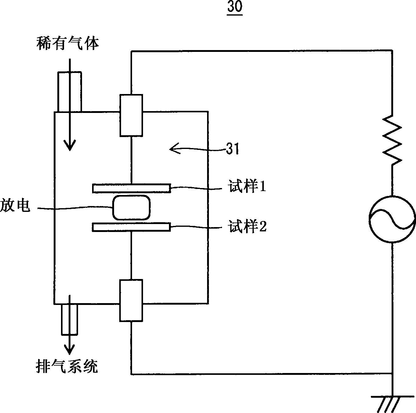
[0214] In the aforementioned , after the plasma treatment, the vacuum chamber is first evacuated to 3×10 -4 Pa, and then filled with argon until it reaches 3700Pa.
[0215] Then, if Figure 41 As shown, an AC voltage of 10 Hz was applied at a peak-to-peak value of 600 V, and the cathode drop voltage of sample A after plasma treatment was measured, and it was 164 V when the Pd product was about 4.1 Torr·cm. Here, P is the air pressure in the vacuum chamber, and d is the distance between the cathode and the anode. In contrast, the cathode drop voltage of metal molybdenum is 206V. Therefore, it can be seen that the cathode drop voltage of sample A after the plasma treatment is 20% lower than that of metal molybdenum.
Embodiment 2
[0217]
[0218] In , Sample B, which is a metal nickel substrate covered with a mayenite compound, was obtained in the same manner except that heat treatment was performed in a hydrogen atmosphere at a gas pressure of 0.1 MPa. The covered portion of Sample B was pale yellow in color and was not conductive in the tester. For the covered part of sample B, the electron density obtained by the measurement of the ESR device is less than 1.0×10 15 cm -3 . Further UV irradiation on the covered part, the H - The electron density is measured after the ions become electrons, and the H - Ion Density, Results H - The ion density is 7.3×10 18 cm -3 . In addition, it can be seen from X-ray diffraction that sample B is only 12CaO·7Al 2 o 3 structure.
[0219] Then, in the , the plasma processing was performed in the same manner except that the time of exposure to plasma was set to 5 seconds. According to X-ray diffraction, the coating of sample B after plasma treatment is only 1...
Embodiment 3
[0223]
[0224] The powder A2 was press-molded at a pressure of 2 MPa to produce a disk-shaped compact with a diameter of 1 cm and a thickness of 2 mm. Furthermore, this molded body was heated to 1350 degreeC in air|atmosphere, and the sintered body was obtained. The obtained sintered body was placed in an alumina container with metal aluminum powder spread on the bottom, and a lid made of alumina was placed on it. Put the covered aluminum oxide container at 10 -3 Heating to 1300°C in a vacuum below Pa to obtain a reduced sintered body. The resulting reduced sintered body was black. It pulverized by the same pulverization method as powder A2, and obtained the black powder with an average particle diameter of 5 micrometers. From the diffuse reflectance spectrum, the electron density of the black powder measured by Kubelka-Munck method is 1×10 21 cm -3 . In addition, it can be seen from X-ray diffraction that the powder is only 12CaO·7Al 2 o 3 structure.
[0225] In ,...
PUM
 Abstract
Description
Claims
Application Information
 - R&D
- Intellectual Property
- Life Sciences
- Materials
- Tech Scout
- Unparalleled Data Quality
- Higher Quality Content
- 60% Fewer Hallucinations
Browse by: Latest US Patents, China's latest patents, Technical Efficacy Thesaurus, Application Domain, Technology Topic, Popular Technical Reports.
© 2025 PatSnap. All rights reserved.Legal|Privacy policy|Modern Slavery Act Transparency Statement|Sitemap|About US| Contact US: help@patsnap.com


