Hydraulic pump assembly of turnover device for automobile cab

A technology of overturning device and cab, which is applied to the upper structure of the truck, vehicle parts, transportation and packaging, etc., and can solve the problems of safety hazards, stopping and keeping the cab in the lowered position, complex structure, etc. Achieve the effect of good sliding seal and simple structure

Inactive Publication Date: 2012-07-11
上海中欧汽车电器有限公司
View PDF5 Cites 11 Cited by
  • Summary
  • Abstract
  • Description
  • Claims
  • Application Information

AI Technical Summary

Problems solved by technology

In the prior art, for example, the "Single-circuit Hydraulic Turning and Lifting Device for Truck Cab" with the notification number CN201280161Y discloses a turning device composed of an oil cylinder assembly and a hydraulic pump assembly, wherein the pump body of the oil pump assembly integrates a plunger , the distribution shaft, the oil suction hole under the plunger is connected with the fuel tank, the oil outlet of the distribution shaft is connected with the pump body hole, the oil inlet of the oil cylinder assembly is connected with the oil outlet of the oil pump assembly with a high-pressure pipe, and the oil outlet is connected with the oil outlet of the pump assembly. The hole system of the distribution shaft and the hole system of the pump body cooperate to form a reversing distribution valve to control the oil inlet or return of hydraulic oil. The lowering of the cab disclosed in this prior art solution depends on its own weight. In order to prevent the sudden burst of the high-pressure oil pipe from causing the For rapid descent, the limited ratchet is installed at the bottom of the oil cylinder, which is not only complicated in structure, but also under normal circumstances (that is, when the high-pressure oil pipe does not burst), the cab cannot control the descending speed during the descent process, which leaves little room for the cab's descending safety. Hidden danger; the hydraulic pump itself cannot control the hydraulic cylinder to stop at a certain descending position as needed during the descending process, and keep it at the descending position, which is not conducive to fixing the descending position at any time during work.

Method used


Image

  • Hydraulic pump assembly of turnover device for automobile cab
  • Hydraulic pump assembly of turnover device for automobile cab
  • Hydraulic pump assembly of turnover device for automobile cab

Examples


Embodiment Construction

[0032] The specific embodiments of the present invention will be described in detail below in conjunction with the accompanying drawings, and the advantages of the present invention and its contribution relative to the prior art will be further clarified.

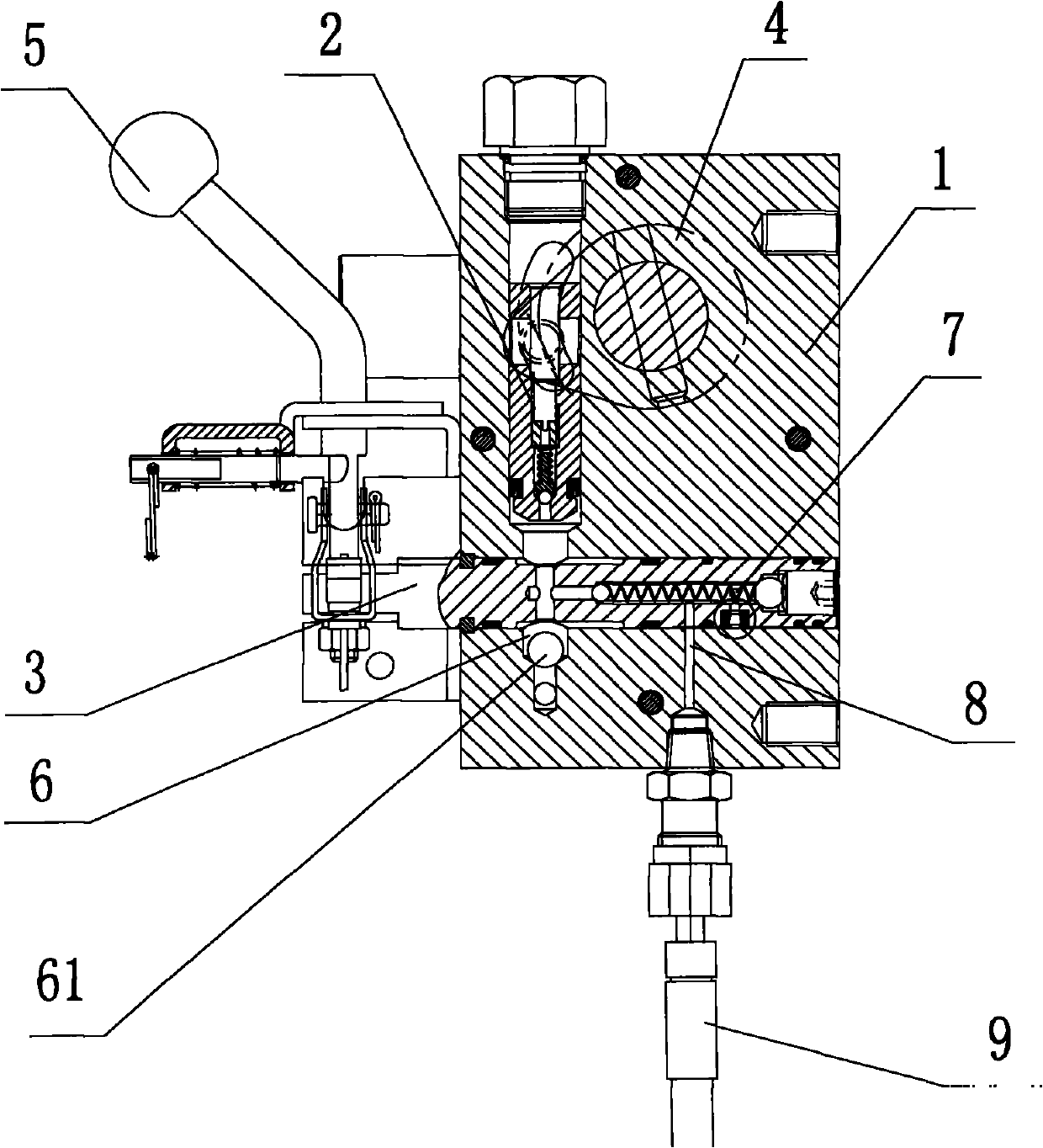
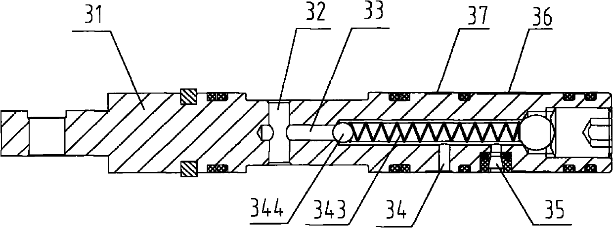
[0033] Such as figure 1 , 2, 3, and 4, one side of the pump body 1 is integrated with the fuel tank 10, and the inside of the pump body 1 is longitudinally integrated with a plunger 2 that slides and seals with the inner wall of the pump body. There is a spherical one-way valve core C21 inside, the spherical one-way valve core C21 is usually a steel ball, the ball seat 22 for fixing the steel ball, the return spring B23 for pressing the ball seat 22, and the screw plug 24 is provided with an oil return channel And threaded with the plunger 2 to compress the return spring B23, which is used to adjust and fix the pressure value of the return spring B23; the rocker arm 4 is integrated on the outside of the pump body 1 and con...


PUM


Abstract

The invention discloses a hydraulic pump assembly of a turnover device for an automobile cab. According to a technical scheme, a pump body integrates a plunger piston, a reversing valve assembly, a rocker arm, an operating handle, an oil absorption cavity, a pump body oil return opening and a pressure oil channel, wherein the reversing valve assembly comprises a valve body, a longitudinal oil inlet hole, a valve cavity, a valve body oil inlet and a valve body oil return opening. The hydraulic pump assembly has a simple structure, is practical, can control the lowering speed of the cab, and can be stopped at any lowering position according to requirements.

Description

technical field [0001] The invention relates to a motor vehicle hydraulic device, in particular to a manual hydraulic turning device for a motor vehicle cab. Background technique [0002] The engine of flat-head trucks is generally designed under the cab, so the cab needs to be turned over when the engine is maintained, and the cab can be lowered after the maintenance is completed. This kind of overturning device is usually supplied by a manual or electric hydraulic pump through a high-pressure pipe to the lower chamber of the hydraulic cylinder to jack up the piston rod to turn the cab upward. The upper chamber of the hydraulic cylinder is switched to communicate with the oil inlet, the manual or electric hydraulic pump presses oil to the upper chamber of the hydraulic cylinder or the piston rod is lowered by the weight of the cab, and the hydraulic oil in the lower chamber of the hydraulic cylinder returns to lower the cab. In the prior art, for example, the "Single-circu...

Claims


Application Information

Patent Timeline
Patent Type & Authority Applications(China)
IPC IPC(8): B62D33/063
Inventor 吴国琳戴宇新
Owner 上海中欧汽车电器有限公司
Why Eureka
Try Eureka