
Laser shock peening method and device using high-pressure gas as constrained layer

A technology of laser shock strengthening and high-pressure gas, which is applied to laser welding equipment, manufacturing tools, welding equipment, etc., can solve the problems of insufficient efficiency, inapplicability, troublesome cleaning, etc., and achieve good restraint, reliable restraint, and simple structure Effect

Inactive Publication Date: 2012-07-11
JIANGSU UNIV
View PDF4 Cites 23 Cited by
  • Summary
  • Abstract
  • Description
  • Claims
  • Application Information

AI Technical Summary

Problems solved by technology

[0004] At present, water and glass are mainly used as the constrained layer, and ice and flexible film are used as the constrained layer in addition; such as China's patent CN1308112C "laser shock treatment method and device with ice as the constrained layer" and CN1404954 "a laser shock treatment method for laser Shock-treated flexible film”; the water-constrained layer device is complex, the operation is complicated, and the uniformity of the thickness of the water-constrained layer cannot be guaranteed. There are certain requirements for the laser parameters, which also have a certain impact on the impact effect, and the synergistic effect is not obvious; the glass-constrained layer is suitable for Poor performance, not suitable for micro-holes, corners, and non-planar areas, and the cost is high, glass fragments will splash when impacting, which poses safety hazards to instruments and personnel, and it is also very troublesome to clean up; the ice-confined layer can Solve the safety hazards of the glass confinement layer, easy to clean, but the ice is easy to melt, which has a certain impact on the experimental device, and the ice confinement layer needs to be prepared on site, which seriously affects the impact continuity and impact efficiency; although the flexible film can solve the above problems Some defects, but because the constrained layer is flexible, the synergy is not as obvious as that of the rigid constrained layer, and the material selection and manufacturing requirements of the flexible film are relatively high, and the cost is relatively high

Method used


Image

  • Laser shock peening method and device using high-pressure gas as constrained layer
  • Laser shock peening method and device using high-pressure gas as constrained layer

Examples


Embodiment

[0032] Prepare five 2024 aluminum alloy samples with a length of 50mm, a width of 50mm, and a thickness of 10mm, which are respectively marked as sample 1, sample 2, sample 3, sample 4 and sample 5; before laser shock treatment, the surface of the sample is selected Grind with 400#-1200 sandpaper, then put it in ethanol for ultrasonic cleaning, dry it with cold wind, use 0.1mm thick American 3M company’s special aluminum foil (one side is an adhesive, and stick to the surface of the sample) as the laser energy for laser impact Absorbing layer, laser pulse energy is 8J, wavelength 1064nm, pulse width 10ns, spot diameter 6mm, single impact; sample 1 is impacted without a constrained layer, and sample 2 is impacted under a water-constrained layer. Sample 3 was impacted under the K9 glass confinement layer, sample 4 was impacted under the high-pressure gas confinement layer (the pressure of the high-pressure gas was controlled at 10MPa), and sample 5 was also impacted under the hig...


PUM


Abstract

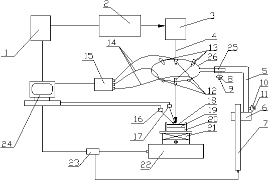
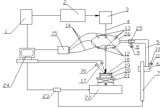
The invention relates to the field of laser processing, in particular to a laser shock peening method and a laser shock peening device using high-pressure gas as a constrained layer. The high-pressure gas serves as the constrained layer; the pressure of the high-pressure gas can be set and adjusted according to the test requirement; the pressure in the whole shocking process is controlled to be unchanged; and the position of a nozzle can be adjusted in real time, so that the jet center of the high-pressure gas, the spot center of laser and the pre-shock treatment position of a workpiece are overlapped, and single-point multi-time shock and multi-point continuous shock on a test sample are realized.

Description

technical field [0001] The invention relates to the field of laser processing, in particular to a laser shock strengthening method and a device thereof using high-pressure gas as a constrained layer. Background technique [0002] Laser Shock Processing (LSP) is a technology that utilizes high power (10 9 W / cm 2 ) short pulse (ns level) laser and the force effect of high pressure shock stress wave (GPa level) generated during the interaction process with materials to improve the surface modification technology of metal mechanical properties, this technology has been used in mechanical engineering, aerospace, micro Widely used in electronics, military and other industries. [0003] Laser shock strengthening can be divided into direct ablation model and constrained ablation model; the shock wave peak pressure obtained by direct laser irradiation on the surface of the material is only a few MPa. Covering with a layer of material transparent to the laser (ie, the constrained l...

Claims


Application Information

Patent Timeline
IPC IPC(8): C21D10/00B23K26/00B23K26/352
Inventor 冯爱新施芬聂贵锋李彬韩振春卢轶郭儒成
Owner JIANGSU UNIV
Learn More