
Condensate-recycling system

A condensate and recycler technology, applied in the field of condensate recycling systems, can solve problems such as heavy accumulation, heat waste, energy waste, etc., and achieve the effect of reducing waste and avoiding waste.

Active Publication Date: 2012-07-11
CHINA TOBACCO GUIZHOU IND
View PDF4 Cites 7 Cited by
  • Summary
  • Abstract
  • Description
  • Claims
  • Application Information

AI Technical Summary

Problems solved by technology

[0003] At present, the condensed water produced by the heat exchange equipment of the cigarette factory production line is generally returned to the condensed water recovery device through the buried pipeline, but because the steam pressure of each production process is different (the maximum steam pressure is not lower than 0.8 at the silk drying machine of the silk production line MPa, and the working pressure of the condensate recovery device is only 0.125MPa), so the condensed water is easy to generate flash steam in the condensed water pipeline, and the leaked steam of some steam traps will also enter the condensed water pipeline, which will make the A large amount of flash steam and leaked steam accumulate in the condensate recovery device, which increases the back pressure in the condensate recovery device, which in turn causes poor drainage of gas-consuming equipment. In order to ensure smooth drainage of gas-consuming equipment, the sealed condensate is usually recovered The device is changed to an open system, and an emptying pipe is added to the condensate recovery device to discharge the flash steam, so that a large amount of heat is wasted in vain, resulting in energy waste

Method used


Image

  • Condensate-recycling system
  • Condensate-recycling system

Examples


Embodiment Construction

[0014] The preferred embodiments of the present invention will be described in detail below with reference to the accompanying drawings.

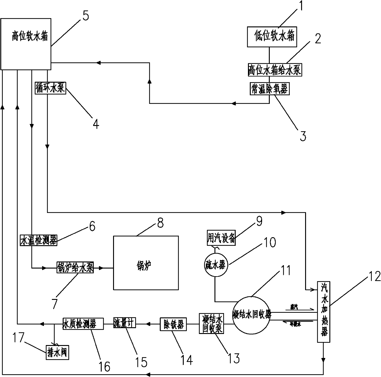
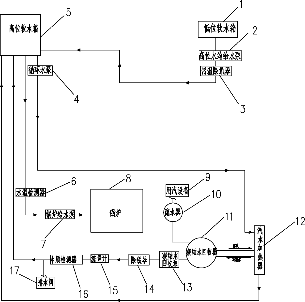
[0015] like figure 1 As shown, the condensed water recycling system includes a boiler 8, a low-level soft water tank 1, a high-level soft water tank 5, a condensate water collector 11 and a soda heater 12, and the low-level soft water tank 1 is connected to the high-level soft water tank 5 through the high-level water tank feed pump 2 , a normal temperature deaerator 3 is arranged on the pipeline connecting the low-level soft water tank 1 and the high-level soft water tank 2. The high-level soft water tank 5 is connected to the boiler through a boiler feed pump 7, and a water temperature detector 6 is provided on the connection pipeline between the high-level soft water tank and the boiler. The condensate recovery device 11 is connected to the steam-using equipment 9 through the steam trap 10 .

[0016] The high-level soft water tank 5 is...


PUM


Abstract

The invention discloses a condensate-recycling system. A top soft water tank is connected with a boiler through a boiler feed pump, a condensate collector is connected with steam-consuming equipment through a steam trap, the top soft water tank is connected with the water inlet of a steam-water heater through a water-circulating pump, the water outlet of the steam-water heater is connected with the top soft water tank, the exhaust outlet of the condensate collector is connected with the steam inlet of the steam-water heater, the condensate discharge outlet of the steam-water heater is connected with the water inlet of the condensate collector, and the water outlet of the condensate collector is connected with the top soft water tank through a condensate-recovering pump. Consequently, the heat of flash steam and leaked steam can be sufficiently utilized, so that the waste of energy can be effectively prevented, meanwhile, the condensate which is produced after steam is cooled can flow into the top soft water tank and is recycled by the boiler, so that the water resource is also effectively utilized and the waste of the water resource is reduced, and therefore the condensate-recycling system can meet the requirement for energy saving and environment-friendliness.

Description

technical field [0001] The invention relates to a condensed water recycling system, in particular to a recycling system for condensed water in tobacco factories. Background technique [0002] In the cigarette production process of cigarette factories, in order to ensure the normal operation of the silk-making line process equipment and HVAC equipment, a large amount of steam needs to be used. As a heat energy carrier, steam will become nearly For saturated condensed water at the same temperature and pressure, since the pressure of steam used is greater than atmospheric pressure, the heat of condensed water can reach 20%-30% of the total heat of steam, and the higher the pressure and temperature, the higher the heat of condensed water. The more, the larger the proportion of the total heat of the steam. It can be seen that 100% of the heat of the condensate is recovered and used effectively has a great potential for energy saving. [0003] At present, the condensed water gene...

Claims


Application Information

Patent Timeline
Patent Type & Authority Applications(China)
IPC IPC(8): F22D1/50F22D11/06
Inventor 李春强毛溪林赵厉罡黄清利任波朱建中伍良社
Owner CHINA TOBACCO GUIZHOU IND
Learn More