Equipment for measuring gas particles in pipeline by laser speckle and method thereof

A technology of laser speckle and measurement equipment, which is applied in the direction of scattering characteristic measurement, fluid velocity measurement, and measurement devices, to achieve the effects of easy maintenance, high data collection efficiency and accuracy, and expanding the gas measurement range

Inactive Publication Date: 2012-07-11
曾春雨
View PDF7 Cites 18 Cited by
  • Summary
  • Abstract
  • Description
  • Claims
  • Application Information

AI Technical Summary

Problems solved by technology

The test object of this system is the nanofluid of iron oxide water, and it does not involve the report of nanoscale gas particles

Method used


Image

  • Equipment for measuring gas particles in pipeline by laser speckle and method thereof
  • Equipment for measuring gas particles in pipeline by laser speckle and method thereof
  • Equipment for measuring gas particles in pipeline by laser speckle and method thereof

Examples


Embodiment 1

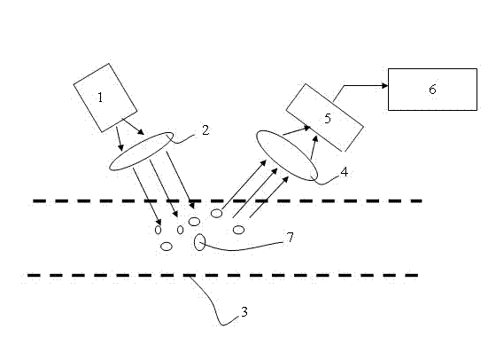
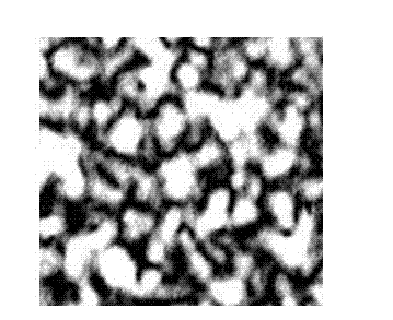
[0028] Example one, as figure 1 As shown, the first lens 2 and the second lens 4 are located on the same side of the gas pipeline 3 under test. At this time, the outgoing light of the laser light source 1 is beam-expanded by the first lens 2 and then enters the measured gas pipeline 3 at a certain angle. The scattering of the gas particles 7 interferes with each other and forms a speckle image on a path separated from the incident light direction at a certain angle. , the optical signal is still emitted from the same side of the gas pipeline 3 to be tested, and is collected by the second lens 4 and then received by the image receiver 5 and transmitted to the image signal processing unit 6 through the optical fiber. The gas speckle diagram formed in the above process is as follows image 3 shown.

Embodiment 2

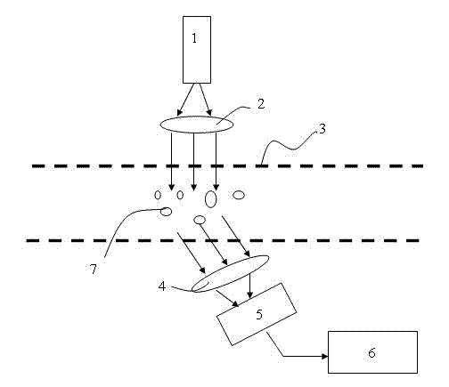
[0029] Example two, as figure 2 As shown, the first lens 2 and the second lens 4 are respectively located on both sides of the gas pipeline 3 under test. At this time, the outgoing light of the laser light source 1 is beam-expanded by the first lens 2 and then vertically incident on the gas pipeline 3 to be measured. When the gas to be measured moves at a certain speed, the nano-gas particles 7 on the path of the laser beam are illuminated and The scattered light is emitted, and the scattering of a large number of nano gas particles 7 interfere with each other and form a speckle image on a path separated by a certain angle from the direction of the incident light. It is then received by the image receiver 5 and transmitted to the image signal processing unit 6 through an optical fiber. The gas speckle diagram formed in the above process is as follows image 3 shown.

[0030] like figure 1 or figure 2As shown, the present invention is like the laser speckle pipeline gas ...


PUM


Abstract

The invention discloses equipment for measuring gas particles in a pipeline by laser speckle. The equipment contains a laser source, an optical system, a gas pipeline to be detected, an image receiver and an image signal processing unit. The optical system comprises a first lens and a second lens. A laser beam emitted from the laser source passes through the first lens for beam expanding and irradiates on the gas particles in the area of the gas pipeline to be detected. An optical signal reflected from the area passes through the second lens, is then received by the image receiver and is finally transmitted to the image signal processing unit. Furthermore, the invention also discloses a relevant measuring method as follows: the image signal processing unit is used to carry out component identification on the gas particles to be detected by the utilization of a nanometer gas particle feature database; and simultaneously, according to the dynamic change of image speckle, motion parameters such as displacement, flow velocity, acceleration and the like of the gas particles are analyzed by the utilization of relevant features acquired by laser speckle statistics. The equipment has high data acquisition efficiency and accuracy. By mechanical design, the equipment is easy to install and maintain. The equipment can be applied in real-time online detection and measurement of various industrial gases.

Description

technical field [0001] The invention relates to the technical field of gas measurement and analysis, in particular to a measurement device and method for realizing the identification and recording of dynamic characteristic parameters of gas particles in pipelines by utilizing the laser speckle pattern of particles and the movement of the speckle pattern. Background technique [0002] Laser speckle measurement technology is a modern optical measurement method developed on the basis of multiple disciplines. It has the advantages of full field, non-contact, high precision, high sensitivity and real-time speed. It is generally used in vibration, displacement, deformation, fracture and roughness. Degree measurement is an effective tool in the field of non-destructive metrology. As early as the 1970s, the laser speckle velocimetry method was introduced into the field of fluid mechanics to measure the velocity of the flow field, and gradually developed into a particle image velocim...

Claims


Application Information

Patent Timeline
Patent Type & Authority Applications(China)
IPC IPC(8): G01N21/47G01P5/26G01P15/093G01C3/00
Inventor 曾春雨
Owner 曾春雨
Why Eureka
Try Eureka