
Detection equipment of film solar cell and method thereof

A technology of solar cells and thin films, applied in the monitoring of photovoltaic systems, photovoltaic power generation, electrical components, etc., can solve the problems of many processes, heavy workload, waste of materials, etc., to avoid secondary pollution, reduce human errors, reduce The effect of production costs

Active Publication Date: 2012-07-11
SHEN ZHEN TRONY SCI & TECH DEV CO LTD
View PDF12 Cites 15 Cited by
  • Summary
  • Abstract
  • Description
  • Claims
  • Application Information

AI Technical Summary

Problems solved by technology

[0002] Thin-film solar cells are currently widely used in small electronic products, such as calculators, garden lights, toys, etc. The thin-film solar cells used in these products are relatively small in size, while the solar cells processed from deposition equipment are large in size , many small-sized solar unit cells (also called unit cells) can be produced on a large thin-film solar panel at the same time, so it is necessary to cut the directly produced large-sized solar cells to obtain them. In the previous production process In general, the character logo is silk-screened first, then cut and inspected, so that the unqualified products are judged at the end, so that the production process of the unqualified products is exactly the same as that of the qualified products, and the unqualified products themselves are unqualified. It was formed before the marking and testing process. The disadvantage of this is that no matter whether the product is qualified or not, it must be marked first, resulting in many technological processes, heavy workload, waste of materials, and increased cost. Marking and testing are carried out separately. For the equipment and methods of separate processes, Chinese patent 200710072812.7 "Solar Cell Laser Marking Equipment" fully discloses the large-format laser marking and marking technology, and Chinese Patent 201020238307.2 "Solar Cell Automatic Testing Device 》The automatic detection technology of monolithic solar cells has also been fully disclosed
Although the Chinese patent No. ZL200910025718.5 discloses a semiconductor device testing and sorting machine, the detection, marking, sorting, and taping of semiconductor devices can be realized on the same machine, although it has a compact structure and high detection efficiency. High advantages, but the device is for a single semiconductor device, complex equipment, high cost, not suitable for testing large-format thin-film solar cells including multiple unit cells

Method used


Image

  • Detection equipment of film solar cell and method thereof
  • Detection equipment of film solar cell and method thereof
  • Detection equipment of film solar cell and method thereof

Examples


Embodiment 1

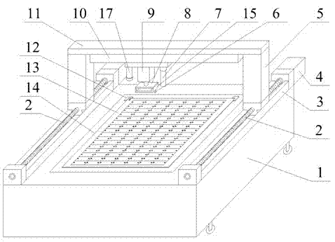
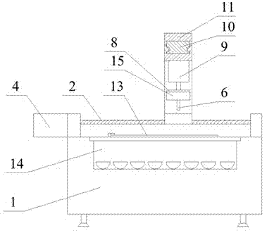
[0043] See figure 1 , figure 2 , the test device for thin-film solar cells is mainly composed of a base 1, a light box 14, an X-axis motion mechanism, a Y-axis motion mechanism, a Z-axis motion mechanism, a detection mechanism, and a marking mechanism. The light box 14 is placed on the base 1, and the Y-axis motion mechanism The movement mechanism is mainly composed of a screw 2, a guide rail 3, a column 5, a beam 11 and a motor 4. The motor 4 drives the screw 2 on both sides to move, and the screw 2 drives the upper column 5 to move along the guide rail 3 in the Y-axis. The beam 11 connected by the two uprights also realizes the Y-axis movement. The X-axis motion mechanism mainly includes a rodless cylinder 10, which is fixed under the beam 11, and the beam 11 drives the rodless cylinder 10 to move in the Y axis, and the rodless cylinder 10 itself can realize the X axis motion. The Z-axis motion mechanism is mainly composed of a cylinder 9 and a fixed plate 8. The cylinder...

Embodiment 2

[0046] The size of the large-format thin-film solar cell core board 13 is 14 inches × 16 inches, including 7 × 7 = 49 unit cell arrays. The unit battery detection method at the same time, the detection mechanism is equipped with 14 detection probes 6, respectively contacting the positive and negative electrodes, the detection probes 6 are compressible spring probes, fixed on the probe fixing plate 15, inkjet marking is adopted, CCD is automatically positioned, Motor 4 is a servo motor. The detection process is as follows: place the thin-film solar cell core board 13 at the limit position of the positioning block 12 fixed on the light box 14, the industrial computer locks the positioning origin through the CCD, and starts to work. The servo motor 4 drives the screw 2 to drive the column 5 Move in the Y direction on the guide rail 3, move the rodless cylinder 10 in the X direction, move the detection probe 6 to the position corresponding to the electrode of the first row of unit...

Embodiment 3

[0048] The size of the large-format thin-film solar cell core plate 13 is 14 inches x 16 inches, including 7 x 7 = 49 unit cell arrays. Simultaneous detection method, 49 groups of 108 detection probes 6 are set on the detection mechanism, respectively contacting the positive and negative poles, the detection probes 6 are compressible spring probes, fixed on the probe fixing plate 15, laser marking is used, and the motor 4 is a servo motor . The detection process is as follows: the thin-film solar cell core board 13 is placed at the limit position of the positioning block 12 fixed on the light box 14, the servo motor 4 drives the screw 2 to drive the column 5 to move in the Y direction on the guide rail 3, and the industrial computer The origin is locked and positioned by the CCD. When starting to work, the cylinder 9 pushes the fixed plate 8 and starts to move downward in the Z direction, so that the detection probe 6 moves downward at the same time and stops after touching th...


PUM


Abstract

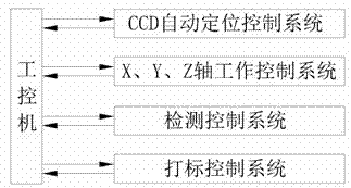
The invention relates to detection equipment of a film solar cell and a method thereof, belonging to the field of solar cell technology. The automatic detection equipment of the film solar cell comprises a workbench and an X-Y-Z shaft motion mechanism. A crossbeam of a Y shaft motion mechanism is connected with an X shaft. The detection equipment is characterized in that: the X shaft is provided with a CCD positioner with automatic origin positioning, a marking mechanism, and a Z shaft with a detection mechanism, a four-in-one machine with integration of positioning, X-Y-Z shaft motion, detection and marking is formed, the four-in-one machine is controlled by an industrial control computer program to detect electrical performance of each unit cell in a film solar cell core plate, and a qualified unit cell in detection is marked with a character. The detection equipment with the integration of positioning, X-Y-Z shaft motion, detection and marking can clearly identify and classify a qualified product and an unqualified product before a cutting procedure, possibility of mixing of the qualified product and the unqualified product in classification is eliminated, a production procedure is saved, and production efficiency is raised.

Description

technical field [0001] The invention relates to a detection device and method for a large-format thin-film solar cell, belonging to the technical field of thin-film solar cells. Background technique [0002] Thin-film solar cells are currently widely used in small electronic products, such as calculators, garden lights, toys, etc. The thin-film solar cells used in these products are relatively small in size, while the solar cells processed from deposition equipment are large in size , many small-sized solar unit cells (also called unit cells) can be produced on a large thin-film solar panel at the same time, so it is necessary to cut the directly produced large-sized solar cells to obtain them. In the previous production process In general, the character logo is silk-screened first, then cut and inspected, so that the unqualified products are judged at the end, so that the production process of the unqualified products is exactly the same as that of the qualified products, a...

Claims


Application Information

Patent Timeline
Patent Type & Authority Applications(China)
IPC IPC(8): G01R31/26H02S50/10
CPCY02E10/50
Inventor 李毅李全相
Owner SHEN ZHEN TRONY SCI & TECH DEV CO LTD
Learn More