Combined dammam grating

A Damman grating and grating technology, which is applied in the field of combined Damman gratings, can solve the problems of a small number of Daman grating beam splitting and limited beam splitting angle, and achieve the effects of uniform light intensity and high diffraction efficiency.

Active Publication Date: 2012-07-11
SHANGHAI INST OF OPTICS & FINE MECHANICS CHINESE ACAD OF SCI
View PDF1 Cites 4 Cited by
  • Summary
  • Abstract
  • Description
  • Claims
  • Application Information

AI Technical Summary

Problems solved by technology

[0004] The purpose of the present invention is to solve the problem that a single Damman grating has a small number of beam splits and a limited beam splitting angle, and proposes a combined Damman grating, which can i

Method used


Image

  • Combined dammam grating
  • Combined dammam grating
  • Combined dammam grating

Examples


Embodiment 1

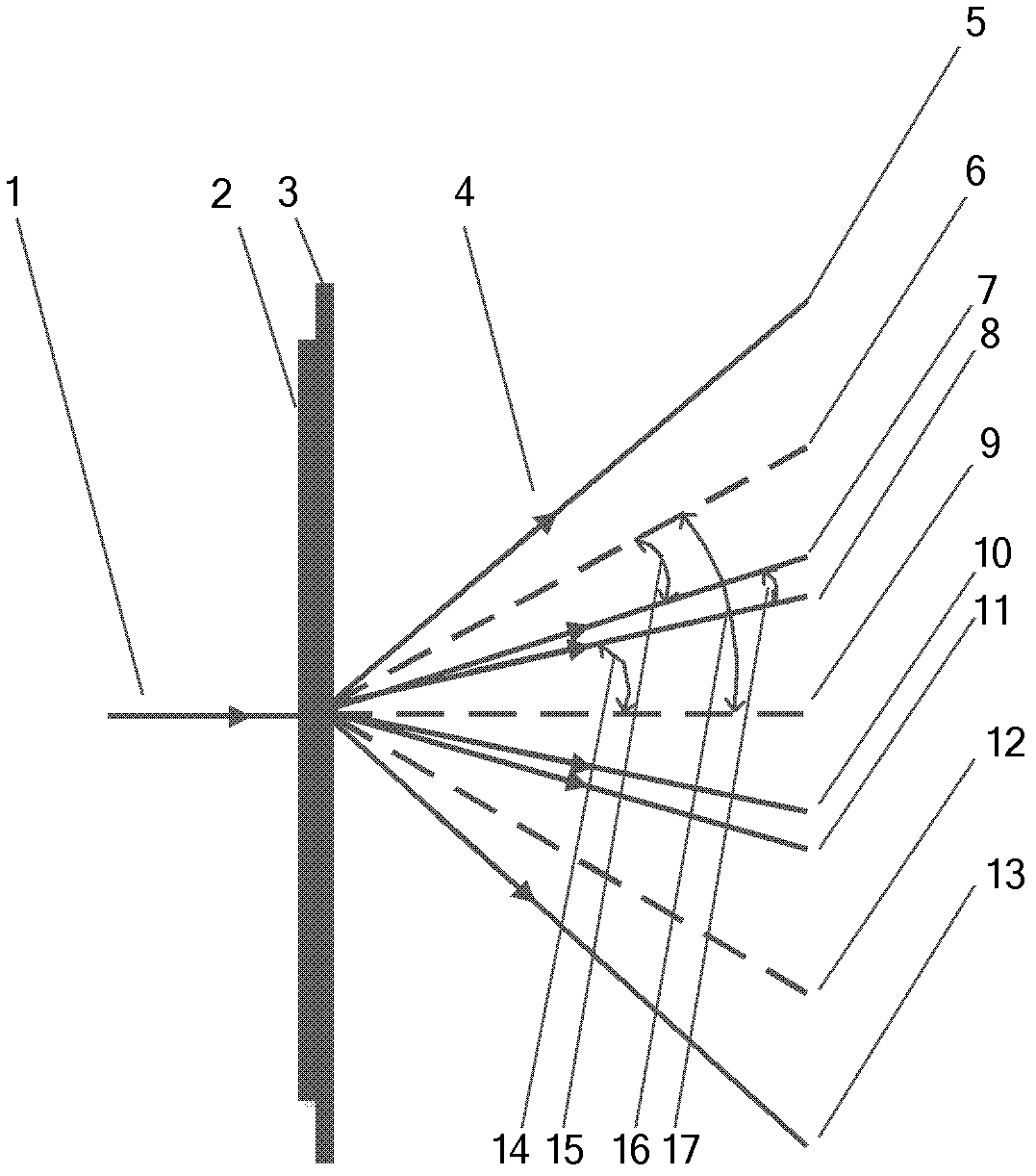
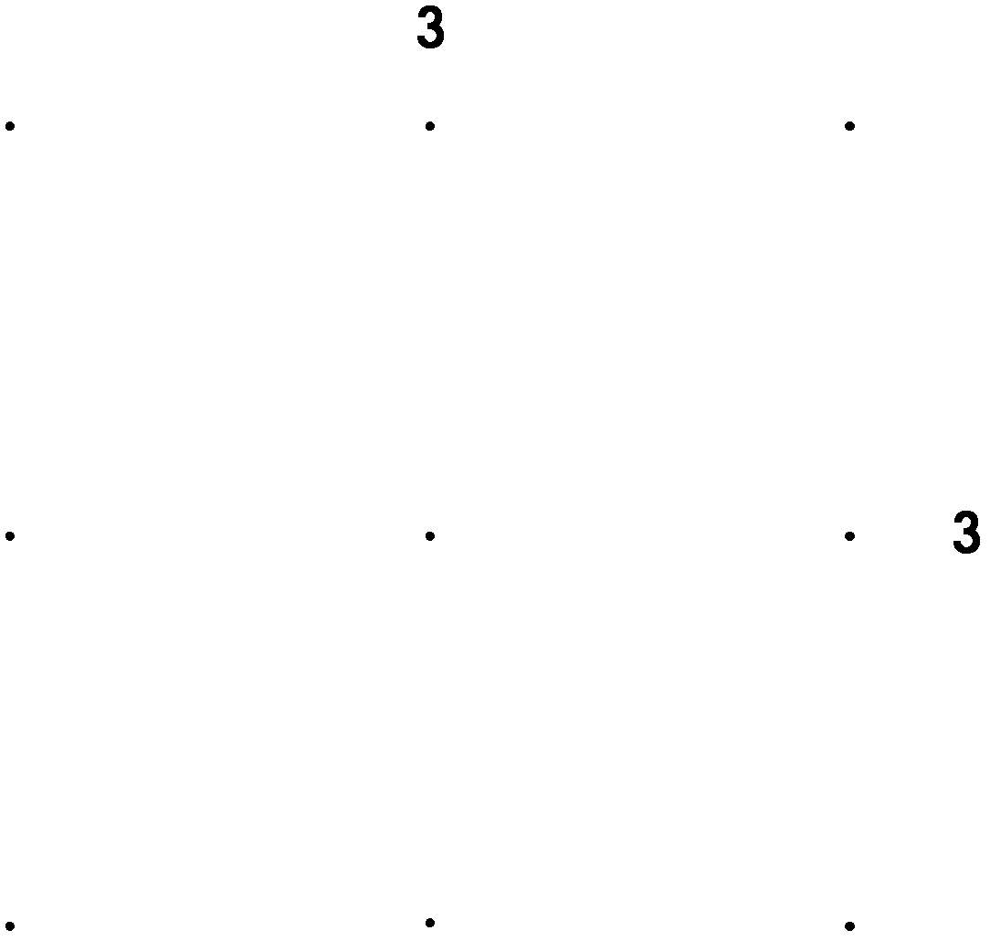
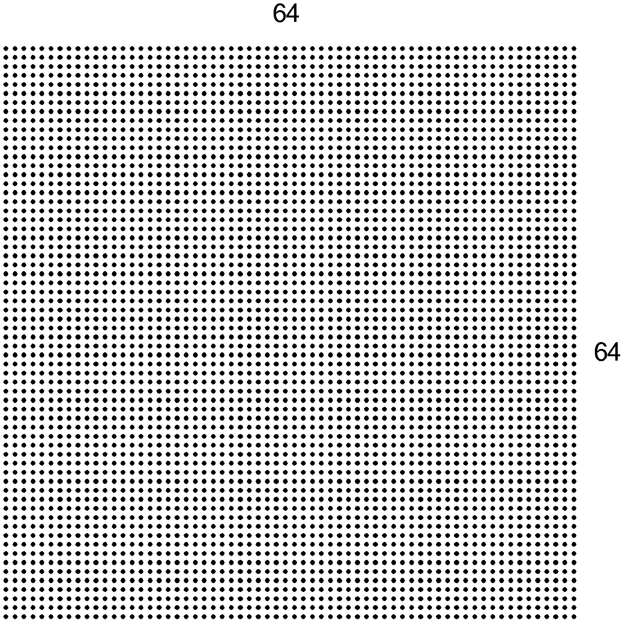
[0026] see figure 1 , figure 1 It is a schematic diagram showing that the combined Damman grating of the present invention is composed of Damman grating 2 and Damman grating 3 to realize a 192X 192 dot matrix. 1 in the figure is the laser beam with a wavelength of λ=532nm, and 2 is the period of realizing 3X3 beam splitting is d 2 = 3.9um odd-numbered Damman grating, the lattice effect is as follows figure 2 As shown, 3 is the period to realize 64X64 beam splitting is d 3 = 500um even-numbered grating, the dot matrix effect is as follows image 3 As shown, the Damman grating 2 and the Damman grating 3 constitute a combined Damman grating.

[0027] The laser beam 1 is vertically incident on the grating 2 and then diffracted by 3X3 laser beams with different incident directions on the 3, and the 3X3 laser beam is diffracted by the grating 3 to form a 192X192 lattice beam 4. The typical beams in the lattice beam 4 are: 5 is the +63-order light diffracted after the +1-order ...

Embodiment 2

[0030] Set the process condition as the minimum processable size is 500nm. Now it is hoped to realize 1X21 dot matrix beam splitting for 532nm wavelength laser with a beam splitting angle of 2 degrees. If a single Damman grating is used, the grating period is about 15.24um, and the minimum feature size is about 198nm, which cannot meet the process conditions. Under the set process conditions, the minimum grating period of the Damman grating is 38.46um, and its maximum beam splitting angle is only 0.79 degrees. Image 6 It is a schematic diagram of a single Damman grating achieving 1X21 beam splitting with a beam splitting angle of 0.79 degrees.

[0031] Therefore, the requirement of 1X21 beam splitting with a beam splitting angle of 2 degrees cannot be achieved by using a single Damman grating, and can only be realized by combining Damman gratings.

[0032] Now use two odd-numbered Damman gratings of 1X3 and 1X7 to realize 1X21 dot matrix beam splitting with a beam splitting...


PUM


Abstract

A combined dammam grating is made by combination of N dammam gratings which meet grating period matching conditions. The grating is obliged to meet the period matching conditions. If the nth dammam grating is an even grating, the dn is required to meet the grating period strict matching condition that 2 sin - 1 (mn lambada/dn) + sin - 1 (2 lambada/dn) = sin - 1 (lambada/dn - 1); if the nth dammam grating is an odd grating, the dn is required to meet the grating period strict matching condition that 2 sin - 1 (mn lambada/dn) + sin - 1 (lambada/dn) = sin - 1 (lambada/dn - 1); and the dn is the period of the nth dammam grating, mn is order of edge diffraction of the nth dammam grating, n is a positive integer and belongs to N, and lambada is incident laser wavelength. By means of the combined dammam grating, beam splitting quantity and beam splitting angle which a single dammam grating can not achieve under same processing conditions can be achieved in terms of incident light multiple diffractions. The combined dammam grating has the advantages that the usage is convenient, cost is low, light spot and light intensity are uniform, and the like. Application range of dammam gratings can be greatly extended, and the combined dammam grating is expected to be widely applied in fields of precision measurement, machine vision, aerospace and the like.

Description

technical field [0001] The invention relates to a Damman grating, in particular to a combined Damman grating to increase the beam splitting number and beam splitting angle of the Damman grating lattice. Background technique [0002] The Dammann grating was invented by Dammann and Gortle in 1971 [Prior Art 1: H. Dammann and K. Gortler, Opt. Comm. 1971, 3(3): 312-315]. As a Fraunhofer-type optical device, the Fraunhofer diffraction pattern produced by the incident light wave through it is a certain number of dot matrix equal-intensity spots, which completely avoids the spectral points caused by the sinc function intensity envelope of the general amplitude grating Uneven distribution of light intensity. In 1995, Zhou Changhe gave the solution of Damman grating from 2 to 64 lattices [Prior Art 2: C.H.Zhou, L.R.Liu, Appl.Opt., 1995, 34(26), 5961~5969], and then designed and Most optical systems are matched with circular Damman gratings, and the influence of phase fabrication er...

Claims


Application Information

Patent Timeline
IPC IPC(8): G02B27/10G02B5/18
Inventor 王少卿周常河韦盛斌贾伟曹红超麻健勇
Owner SHANGHAI INST OF OPTICS & FINE MECHANICS CHINESE ACAD OF SCI
Why Eureka
Try Eureka