Optical waveguide switch

A technology of optical waveguide and switch, applied in the field of optical waveguide switch using MZI structure, can solve the problems of unreachable, high extinction ratio, light attenuation, etc., and achieve the effect of improving device efficiency and high extinction ratio

A technology of optical waveguide and switch, applied in the field of optical waveguide switch using MZI structure, can solve the problems of unreachable, high extinction ratio, light attenuation, etc., and achieve the effect of improving device efficiency and high extinction ratio

CN102566090AActive Publication Date: 2012-07-11SHANGHAI SILIGHT TECH

Image

  • Optical waveguide switch
  • Optical waveguide switch
  • Optical waveguide switch

Examples


Embodiment Construction

[0019] Below by specific embodiment and in conjunction with accompanying drawing, the present invention is described in detail:

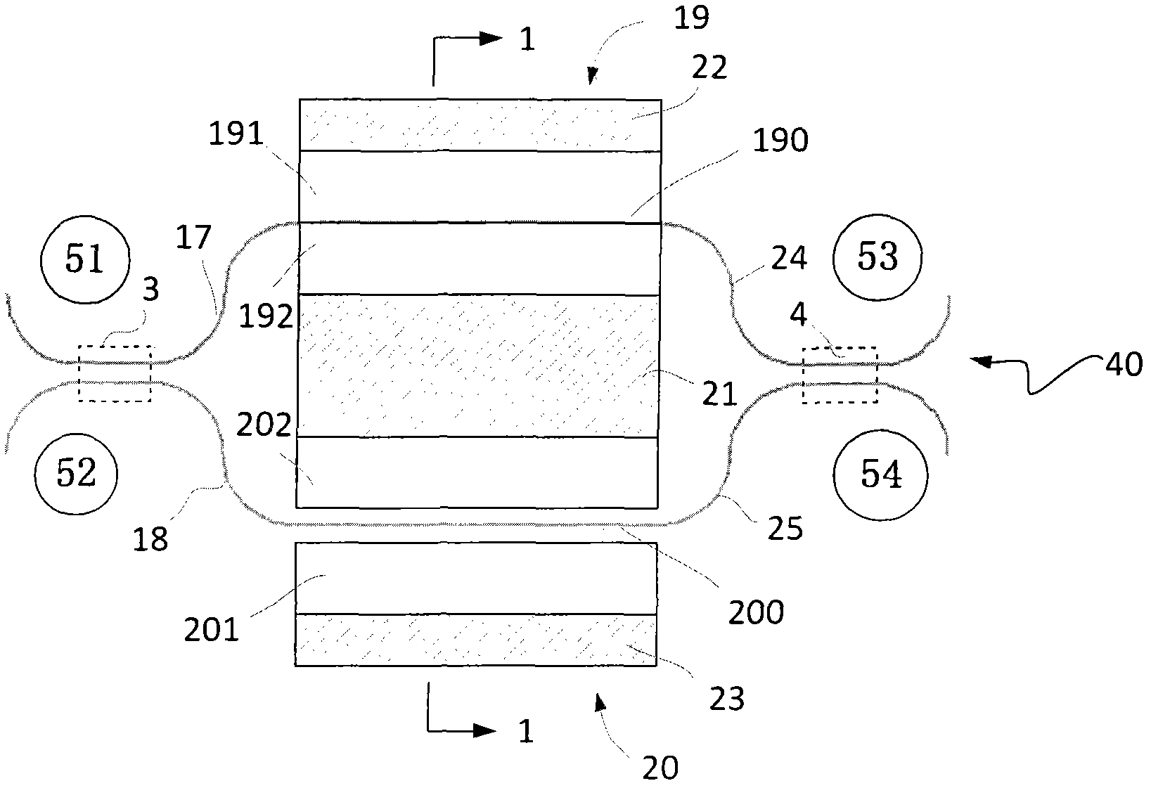
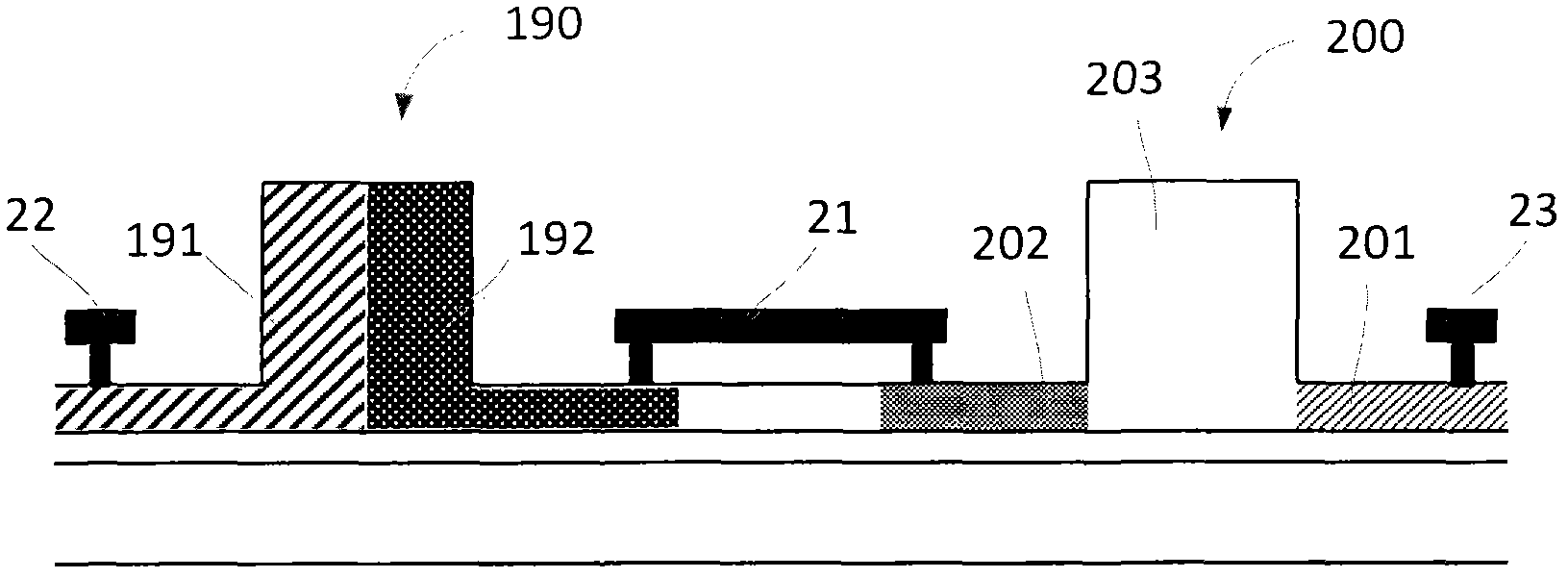
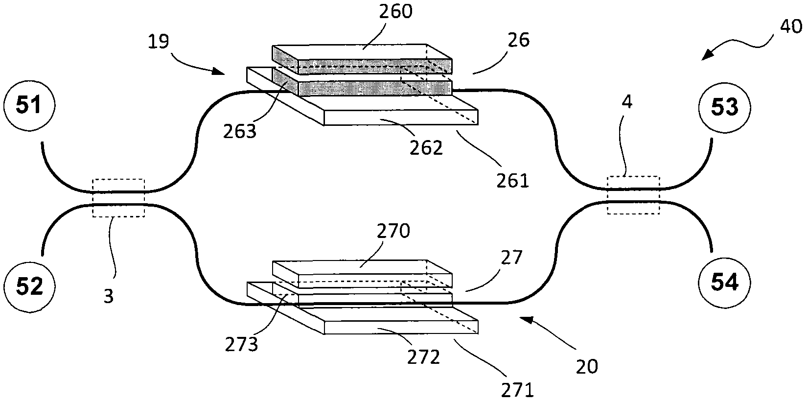
[0020] The invention discloses an optical waveguide switch with a high extinction ratio using an asymmetric semiconductor-based waveguide MZI structure, wherein the two arms of the MZI structure adopt different waveguide container structures: in the waveguide container used by one arm, background ions The concentration is high, mainly to achieve amplitude modulation; in the waveguide container used in the other arm, the concentration of background ions is low, mainly to achieve phase modulation. The PN junction and PIN junction on the optical waveguide are two special cases of waveguide capacitors that can realize the aforementioned functions. A PN junction has a higher background ion concentration, while a PIN junction has a lower background ion concentration. The "higher" or "lower" here is relative, that is, one of the background ion concentrati...


PUM


Abstract

Techniques are described to form an optical waveguide switch that could reach a very high extinction ratio. In particular, this disclosure describes an asymmetric MZI, in which different waveguide capacitor structures are used in two arms of the MZI: a first arm with a waveguide capacitor to achieve the mainly phase modulation and a second arm with a waveguide capacitor to achieve mainly the magnitude modulation, respectively. Using the asymmetric MZI in accordance with this disclosure, one can design an algorithm to achieve almost unlimited extinction ration during the switching operation.

Description

technical field [0001] The invention relates to an optical waveguide switch, in particular to an optical waveguide switch adopting an MZI structure. Background technique [0002] It is a common technique to construct an optical waveguide switch or modulator using a Mach-Zehnder interferometer (MZI) structure. In US Pat. No. 7,817,881, the concept of a waveguide container is introduced. Free carriers can be stored in the waveguide core of this waveguide container to modulate the refractive index of the waveguide material. [0003] In silicon photonics, the free carrier dispersion effect is applied to modulate the refractive index of silicon, so MZI structures can be used to form switches or amplitude modulators. However, in the free carrier dispersion effect, the injected free carriers can affect not only the real part of the refractive index, but also the imaginary part of the refractive index, that is, it will cause light attenuation while modulating the phase. Due to the...

Claims


Application Information

Patent Timeline
11 Jul 2012
Publication
CN102566090A
IPC
G02F1/025; G02F1/01
CPC
G02F1/3136; G02B6/35; G02F1/01; G02F1/2257; G02F1/025; G02B2006/12159; G02B2006/12145; G02B2006/12142
Inventors
李冰