

Design technology of horizontal polarization omnidirectional antenna with adjustable lobe elevation angle
An omnidirectional antenna and leveling technology, which is applied to antenna unit combinations with different polarization directions, antenna supports/mounting devices, and structural forms of radiation elements, etc., can solve the problem of non-adjustable antenna pitch beam pointing and antenna impedance matching difficulties, etc. problem, to achieve the effects of simple beam pointing adjustment, reduced matching difficulty, and increased gain
- Summary
- Abstract
- Description
- Claims
- Application Information
AI Technical Summary
Problems solved by technology
Method used
Image

Examples
Embodiment 1
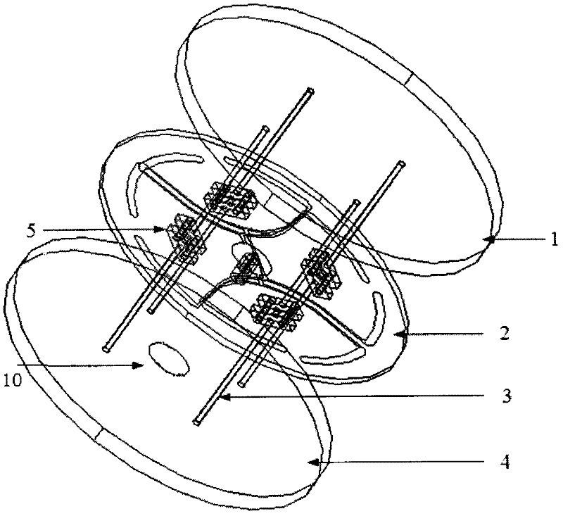
[0030] see figure 1 , a horizontally polarized omnidirectional antenna with adjustable lobe elevation angle. The whole antenna includes a metal reflector 1 at the top, an omnidirectional microstrip antenna 2 , a polytetrafluoroethylene dielectric column 3 , and a metal reflector 4 at the bottom. The middle of each medium column is connected by a medium flange 5 . The omnidirectional microstrip antenna is fixed between the upper and lower dielectric flanges, and the dielectric column is inserted into the mounting hole of the metal plate to fix it. Both the upper and lower metal plates have a diameter of 90 mm and a thickness of 2 mm. A perforation 10 with a diameter of 12mm is provided on the lower metal plate, through which the coaxial cable for feeding passes.
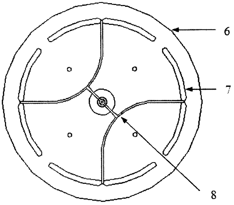
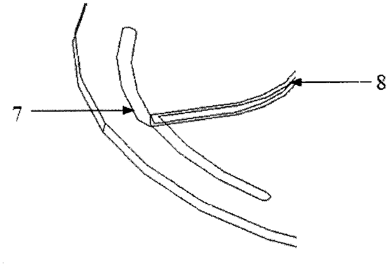
[0031] Such as figure 2 As shown, the omnidirectional microstrip antenna 2 is composed of a dielectric plate 6 , four microstrip dipoles 7 and a feed network 8 . Four microstrip dipoles are evenly etched on the ...
Embodiment 2
[0042] A preferred embodiment of the present invention is an S-band horizontally polarized omnidirectional antenna whose elevation plane points to 60 degrees. This antenna is obtained by increasing the diameter of the metal plate below the antenna in Embodiment 1 to 200 mm. The radiation pattern of the elevation plane at the center frequency of 2.85GHz is as follows Figure 12 , it can be seen from the figure that the antenna beam on the elevation plane points to 60 degrees.
Embodiment 3
[0044] A preferred embodiment of the present invention is Figure 13 , is a binary linear array applied to the S-band omnidirectional antenna. This antenna is composed of two antenna units in Embodiment 1 superimposed in the axial direction, and the two units can be fed with equal amplitude and same phase to increase the gain in the elevation plane.
PUM
| Property | Measurement | Unit |
|---|---|---|
| Diameter | aaaaa | aaaaa |
| Diameter | aaaaa | aaaaa |
Abstract
Description
Claims
Application Information