Multi-polarization microstrip patch antenna loading zero-order resonator

A technology of microstrip patch antenna and zero-order resonance, which is applied to antennas, electrical components, and radiation element structures, can solve problems such as large size, narrow lobe width, and complex structure, and achieve convenient size, easy adjustment, The effect of good radiation properties

Active Publication Date: 2014-05-07
广州桑瑞科技有限公司
View PDF9 Cites 0 Cited by
  • Summary
  • Abstract
  • Description
  • Claims
  • Application Information

AI Technical Summary

Problems solved by technology

Single-polarized antennas are often affected by the environment, antenna placement, etc. during use, so that the receiving effect cannot be guaranteed. Therefore, people invented multi-polarized antennas to overcome the defects of single-polarized and ensure the quality of transmission and reception.
Multi-polarized antennas are mostly combined antennas, which are formed by combining multiple single-polarized antennas with different polarization directions at the same frequency, such as patent CN102099963A. Large size and complex structure
[0003] The microstrip antenna has a light weight, small volume, and thin planar structure. It is easy to make a conformal antenna, low in manufacturing cost, and easy to mass produce. Therefore, it is widely used. The traditional patch antenna has a single polarization direction, which is the horizontal direction of the dielectric substrate. , the pattern is concentrated upwards, the lobe width is narrow, and the horizontal plane radiation is insufficient. On this basis, if a vertically polarized antenna with the same low-profile microstrip structure can be added, a low-profile and small-sized microstrip multi-polarization can be achieved. antenna

Method used


Image

  • Multi-polarization microstrip patch antenna loading zero-order resonator
  • Multi-polarization microstrip patch antenna loading zero-order resonator
  • Multi-polarization microstrip patch antenna loading zero-order resonator

Examples


Embodiment

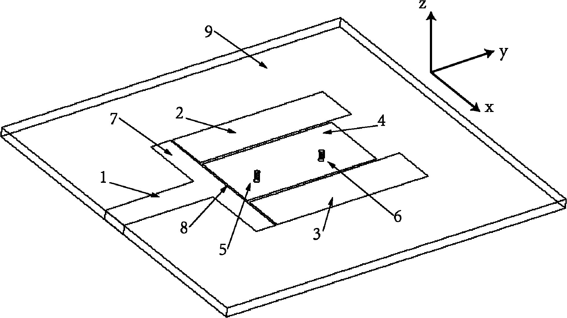
[0028] The structure diagram of the multi-polarized microstrip patch antenna loaded with zero-order resonator in the present invention is as follows figure 1 As shown, it includes an upper layer microstrip structure, an intermediate dielectric substrate 9 with a relative permittivity of 1-100 and a thickness of 0.1mm-5mm, and a bottom metal floor; the upper layer microstrip structure is arranged on the intermediate dielectric substrate 9, which includes a 50 ohm The microstrip transmission line 1, the coupling feeding part 7 and the antenna main body. The microstrip transmission line 1 is vertically connected to the coupling feeding part 7, and the antenna main body and the microstrip transmission line 1 are respectively arranged on both sides of the coupling feeding part 7; there is a gap 8 between the antenna main body and the coupling feeding part 7. Among them, the antenna body is composed of rectangular microstrip patch antennas 2 and 3 and a square second-order mushroom-...


PUM


Abstract

The invention provides a multi-polarization microstrip patch antenna loading a zero-order resonator. The antenna comprises an upper-layer microstrip structure, a middle medium base plate and a bottom-layer metal floor, wherein the upper-layer microstrip structure is arranged on one surface of the middle medium base plate and comprises a microstrip transmission line, a coupling feed part and an antenna main body; the microstrip transmission line is vertically connected with the coupling feed part; the antenna main body and the microstrip transmission line are arranged at the two sides of the coupling feed part respectively; a gap is reserved between the antenna main body and the coupling feed part; the antenna main body consists of two microstrip patch parts and a zero-order resonance part; and the zero-order resonance part is arranged between the two microstrip patch parts and consists of an upper-layer microstrip patch and a grounding metal column vertically arranged between the upper-layer microstrip patch and the middle medium base plate. In the antenna provided by the invention, by combining the traditional microstrip patch antenna with a second-order mushroom type zero-order resonator, the shortcomings of respective polarization direction and radiation patterns of the traditional microstrip patch antenna and the second-order mushroom type zero-order resonator are overcome, so that good radiation characteristic is realized.

Description

technical field [0001] The invention relates to the technical field of miniaturized antennas in wireless communication, and more specifically, relates to a multi-polarization microstrip patch antenna loaded with a zero-order resonator. Background technique [0002] With the rapid development of mobile communication, antennas are used as transceiver devices of wireless communication equipment, and people put forward higher and higher requirements for their performance. Single-polarized antennas are often affected by the environment and antenna placement during use, so the receiving effect cannot be guaranteed. Therefore, people invented multi-polarized antennas to overcome the defects of single-polarized and ensure the quality of sending and receiving. Multi-polarized antennas are mostly combined antennas, which are formed by combining multiple single-polarized antennas with different polarization directions at the same frequency, such as patent CN102099963A. The size is lar...

Claims


Application Information

Patent Timeline
Patent Type & Authority Patents(China)
IPC IPC(8): H01Q13/08H01Q1/38
Inventor 褚庆昕于洪泽
Owner 广州桑瑞科技有限公司
Why Eureka
Try Eureka