
Double-fed wind power generation high-voltage through control structure, and generator and generation system providing with double-fed wind power generation high-voltage through control structure

A technology of doubly-fed wind power generation and wind power generator, applied in the field of doubly-fed wind power generators and doubly-fed wind power generation systems, which can solve problems such as failure to meet the requirements of grid-connected guidelines

Active Publication Date: 2012-07-11
SUNGROW POWER SUPPLY CO LTD
View PDF9 Cites 28 Cited by
  • Summary
  • Abstract
  • Description
  • Claims
  • Application Information

AI Technical Summary

Problems solved by technology

In order to avoid these problems and protect the converter, the wind turbine can be automatically disconnected from the grid, and then connected to the grid after the fault is restored, but this off-grid strategy can no longer meet the requirements of the grid-connected guidelines for large-scale wind farm power generation.

Method used


Image

  • Double-fed wind power generation high-voltage through control structure, and generator and generation system providing with double-fed wind power generation high-voltage through control structure
  • Double-fed wind power generation high-voltage through control structure, and generator and generation system providing with double-fed wind power generation high-voltage through control structure
  • Double-fed wind power generation high-voltage through control structure, and generator and generation system providing with double-fed wind power generation high-voltage through control structure

Examples


Embodiment Construction

[0035] In order to make the object, technical solution and advantages of the present invention clearer, the present invention will be further described in detail below in conjunction with the accompanying drawings and embodiments. It should be understood that the specific embodiments described here are only used to explain the present invention, not to limit the present invention.

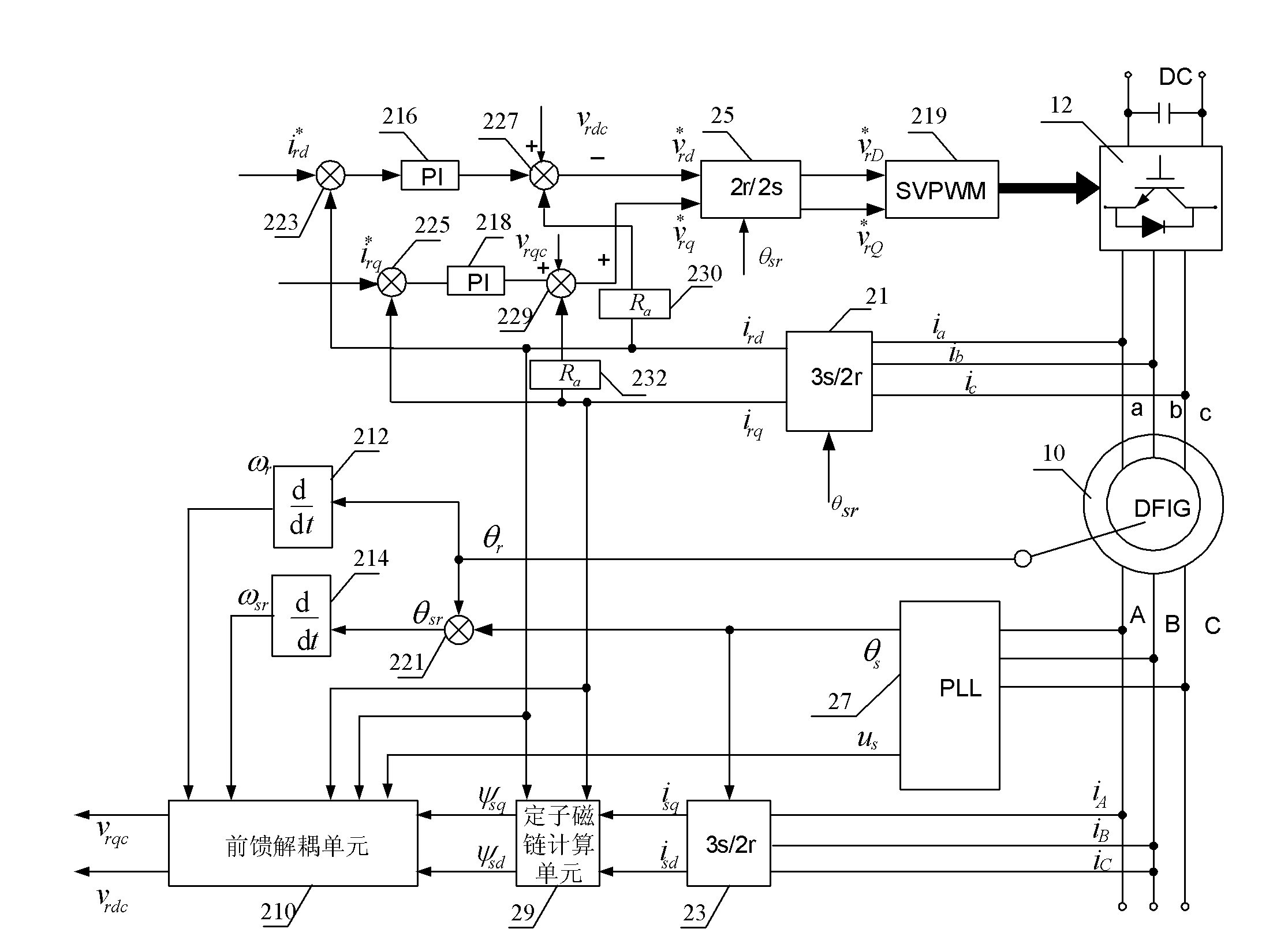
[0036] see figure 1 , which is a structural diagram of the high-voltage ride-through control of doubly-fed wind power generation based on virtual resistance provided by a preferred embodiment of the present invention. The doubly-fed wind power generation high voltage ride-through control structure is applied to the doubly-fed generator 10, which is one of the generators in the doubly-fed wind power generation system.

[0037] The doubly-fed wind power generation high-voltage ride-through control structure includes a first coordinate conversion unit 21, a second coordinate conversion unit 23, a thi...


PUM


Abstract

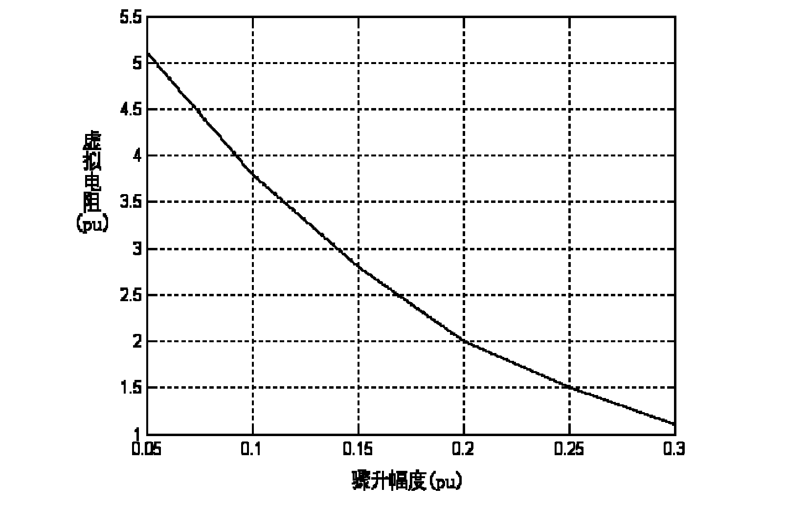
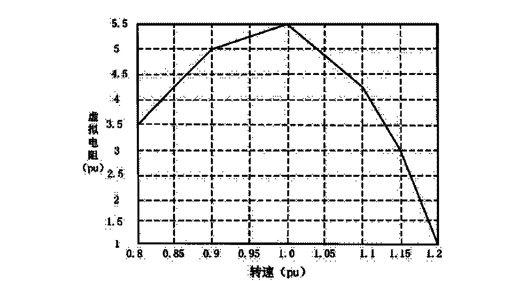
The invention relates to a double-fed wind-power generation high-voltage through control structure, wherein a control structure of a rotor side virtual resistor is formed by guiding a feedback factor Ra into a current feedback channel of a rotor, stacking a product obtained by multiplying feedback current of a d shaft and a q shaft of the rotor on output of a rotor excitation and torque current regulator in rotor excitation control of a double-fed wind power generation. The double-fed wind-power generation high-voltage through control structure has the advantages of reducing the impaction of current and electromagnetic torque of the rotor of a generator when the voltage of power grid suddenly rises and avoiding frequent operation of a crowbar circuit, wherein the virtual resistor can flexibly change according to suddenly rising extent of the power grid rotor and current rotation speed, and when voltage of the rotor is ensured to be not over than an allowable value of an converter rotor, the oscillation of the current and the electromagnetic torque of the rotor is restrained to a maximum extent, so that the optimal control of the generator is realized when the voltage of the power grid rises suddenly. The invention further relates to a double-fed wind power generator and a double-fed wind power generation system with the double-fed wind-power generation high-voltage through control structure.

Description

technical field [0001] The invention relates to the field of wind power generation, in particular to a doubly-fed wind power generation high-voltage ride-through control structure, a doubly-fed wind power generator and a doubly-fed wind power generation system having the doubly-fed wind power high-voltage ride-through control structure. Background technique [0002] With the continuous expansion of wind farm scale and wind power generation capacity, when the grid fails, if the wind turbine is separated from the grid, if it cannot provide frequency and voltage support to the grid in the case of grid failure like conventional energy sources, then It may lead to a serious chain reaction and seriously affect the stable operation of the power grid. In an actual wind farm system, a single-phase-to-ground fault may cause a surge in grid voltage, and the sudden removal of wind farm loads may also cause a surge in grid voltage, and a large input capacitor compensator may also cause a...

Claims


Application Information

Patent Timeline
IPC IPC(8): H02P21/14
Inventor 曹仁贤张兴屠运武谢震余勇杨淑英汪令祥宋海华
Owner SUNGROW POWER SUPPLY CO LTD
Learn More