Wireless signal detection method based on periodogram

A technology of signal detection and periodogram, applied in the direction of transducer circuit, transmission monitoring, sensor components, etc., can solve the problems of narrow-band interference and wireless microphone signal distinction, high false alarm rate, etc.

Active Publication Date: 2012-07-11
UNIV OF SCI & TECH OF CHINA
View PDF2 Cites 6 Cited by
  • Summary
  • Abstract
  • Description
  • Claims
  • Application Information

AI Technical Summary

Problems solved by technology

[0003] The present invention provides a wireless microphone signal detection method based on a periodogram, which is used to solve the problem that the existing wireless microphone signal detection...

Method used


Image

  • Wireless signal detection method based on periodogram
  • Wireless signal detection method based on periodogram
  • Wireless signal detection method based on periodogram

Examples


Embodiment 1

[0085] This embodiment describes the system simulation based on the periodogram wireless microphone detection method. The simulation is carried out based on the MATLAB environment, and the specific simulation steps are as follows:

[0086] 1) Generate a sinusoidal continuous wave signal and a frequency modulated (FM) wireless microphone signal, and then perform down-conversion, low-pass filtering, and down-sampling to obtain a baseband discrete-time signal x[n].

[0087] 2) Set the signal-to-noise ratio SNR, frequency modulation factor β and calculate T p The window length L and other performance parameters.

[0088] 3) Use preprocessing algorithm and detection algorithm to process the signal.

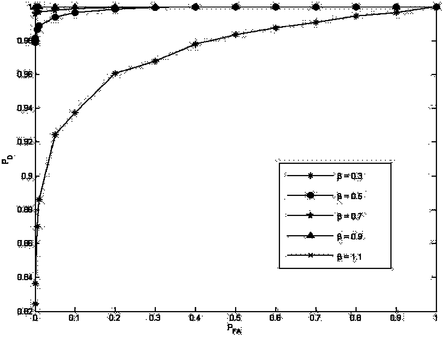
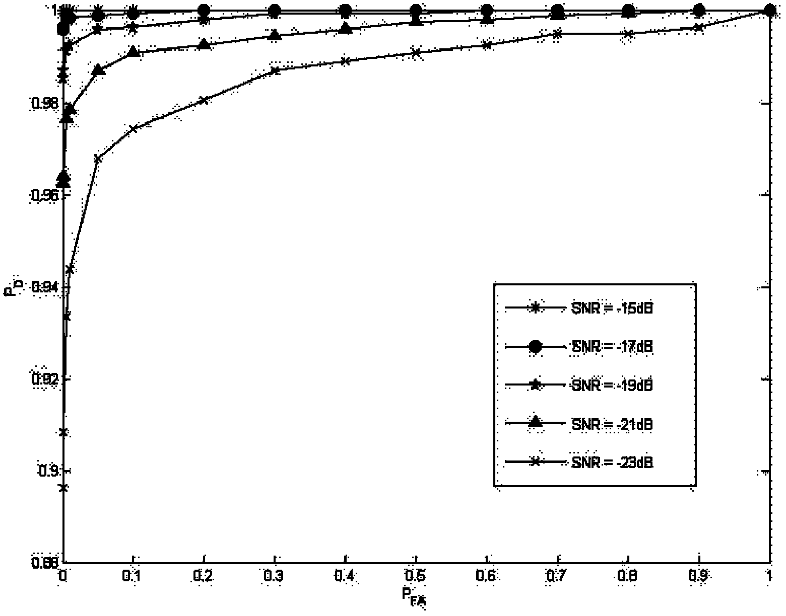
[0089] 4) Draw performance curves under different parameters

[0090] attached figure 2 , image 3 and Figure 4 It is the performance curve obtained by simulation, as can be seen from the figure, for the wireless microphone signal of β=0.7, when L is taken as 11 and the false a...

Embodiment 2

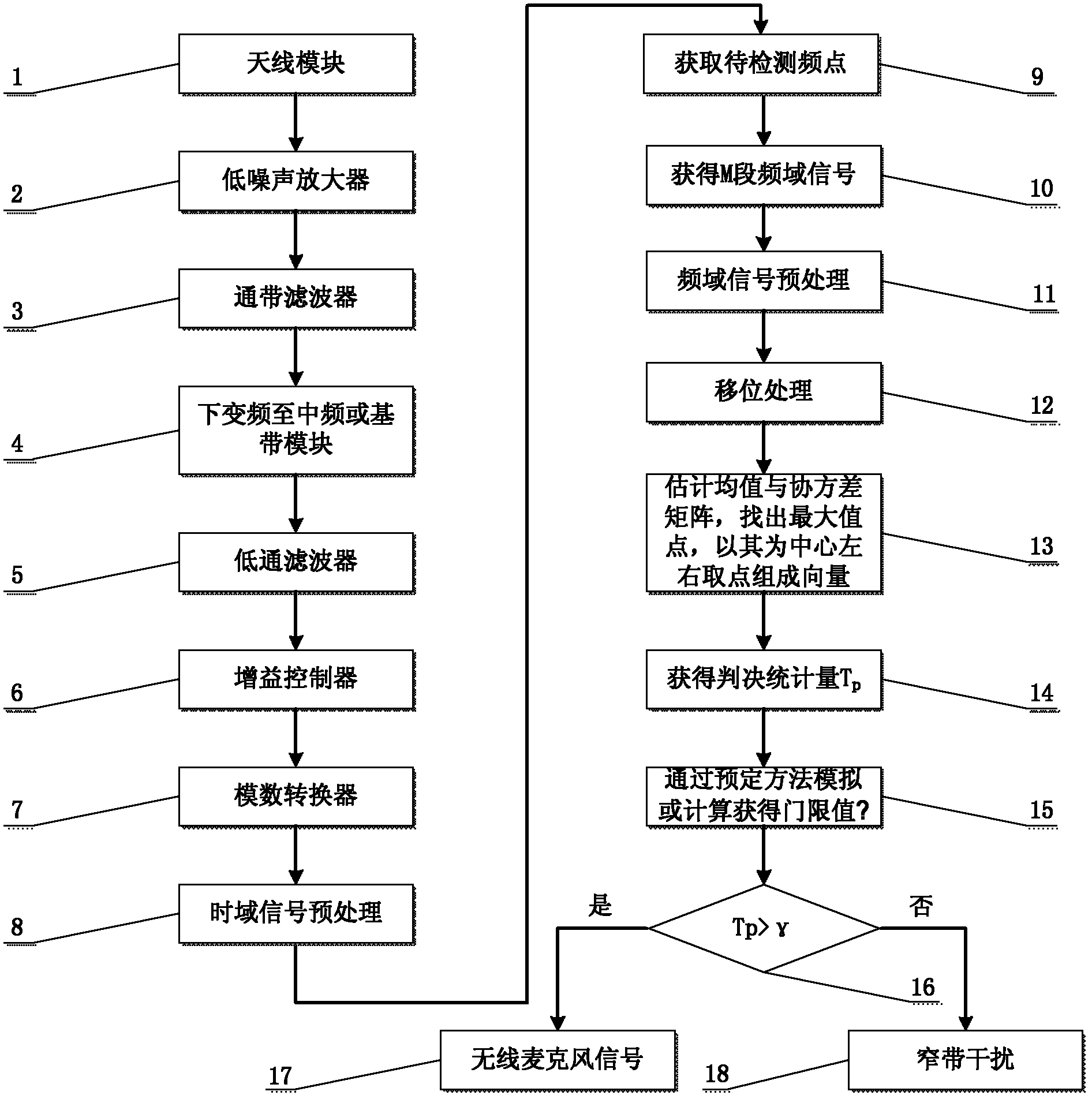
[0092] This embodiment describes the actual system implementation of the periodogram-based wireless microphone detection method. The actual system architecture 1 is attached Figure 5 As shown: the signal received by the antenna module 101 is sent to a low-noise amplifier (LNA) 102, and the amplified signal passes through a band-pass filter (BPF) 103, whose bandwidth can be adjusted according to actual needs, and then the filtered signal is sent to Orthogonal down-converter 105, using the frequency points in the selected TV band as the frequency of the local oscillator 104 to perform quadrature down-conversion processing on the signal, and then obtain IQ two-way signals, and then let the two-way signals pass through low-pass filtering with a certain bandwidth (LPF) 106 and intermediate frequency amplifier (IF Amp) 107 and send the IQ two-way signal that puts out in the analog-to-digital converter (ADC) 109, and finally send the two-way digital signal that ADC109 comes out in t...


PUM


Abstract

The invention provides a wireless microphone signal detection method based on a periodogram, which is used for solving the problem of incapability of distinguishing narrow band interference from a wireless microphone signal in the conventional detection method. The method comprises the following steps of: acquiring a time-domain digital signal needed by detection through an antenna module, a radio-frequency front-end module, an analog to digital conversion module and a time-domain signal preprocessing module; finishing detection of a microphone signal in a frequency domain, i.e., computing to obtain the average value of periodograms of M segments of time-domain digital signals to be detected, performing displacement processing on the average value to obtain displacement vectors, estimating the average value and a covariance matrix of the displacement vectors, finding a maximum value point in the displacement vectors, and selecting a plurality of points from the left and right of the maximum value point serving as a center to constitute an information vector; computing the information vector by using a decision theory to obtain a decision statistic; and simulating or computing a threshold value through a preset method, determining as a narrow band interference if the statistic is smaller than the threshold value according to judgment, otherwise, determining as a wireless microphone signal.

Description

technical field [0001] The invention belongs to the technical field of cognitive radio, and is specifically applied to the detection of low-power wireless microphone signals in blank digital TV band perception. Background technique [0002] The US Federal Communications Commission (FCC) stipulates that TV white space sensing devices must be able to detect wireless microphone signals with a signal strength of -107dbm. Under such a low signal strength, the narrow-band interference caused by stray radiation, leakage, intermodulation, etc. is very similar to the microphone signal, and the existing detection methods do not distinguish the narrow-band interference from the wireless microphone signal, resulting in extremely high false alarm rate, which has led to a sharp decline in the number of available TV white space. Contents of the invention [0003] The present invention provides a wireless microphone signal detection method based on a periodogram, which is used to solve t...

Claims


Application Information

Patent Timeline
IPC IPC(8): H04B17/00H04R3/00
CPCH04B17/005H04B17/00H04R3/00H04R29/004H04B17/336H04B17/345H04R2420/07
Inventor 张韬韬张文逸孙欢欢
Owner UNIV OF SCI & TECH OF CHINA
Why Eureka
Try Eureka