
Manufacturing method of machine parts excellent in rolling fatigue life

一种滚动疲劳寿命、机械部件的技术,应用在发动机元件、抗离心力的转动部件、机械设备等方向,能够解决破损、短寿命、不能够充分实现机械部件和装置等问题,达到提高滚动疲劳寿命的效果

Active Publication Date: 2016-02-10
SANYO SPECIAL STEEL COMPANY
View PDF10 Cites 0 Cited by
  • Summary
  • Abstract
  • Description
  • Claims
  • Application Information

AI Technical Summary

Problems solved by technology

[0006] In addition, even if steel materials made of such high-cleanliness steel are used for mechanical parts and devices, it is not possible to sufficiently suppress the short life and breakage of these mechanical parts and devices.

Method used


Image

  • Manufacturing method of machine parts excellent in rolling fatigue life
  • Manufacturing method of machine parts excellent in rolling fatigue life
  • Manufacturing method of machine parts excellent in rolling fatigue life

Examples


Embodiment 1

[0036] As an example of the present invention, conditions and obtained results will be described. First, Table 1 shows the component composition of the test material used as the steel type of the ring-shaped base material 2 .

[0037] Table 1

[0038] Components of the test material (unit is mass %)

[0039]

[0040] In this example, the test materials of the steel types shown in Table 1 were implemented. First, the molten steel is oxidized and refined in an arc melting furnace, then reduced and refined in a ladle refining furnace (LF), and degassed by a circular vacuum degasser (RH) to reduce the oxygen content in the molten steel , the molten steel is manufactured into steel ingots by continuous casting. This steel ingot is hot-rolled as usual to form a steel material, and after that, a steel pipe is formed by a three-roll mill, and a conventional heat treatment for spheroidizing is prepared.

[0041] Cut the steel pipe composed of the test material shown in Ta...

Embodiment 2

[0054] A test piece was produced in the same manner as in Example 1 except that a hot forged ring was produced instead of the steel pipe. The method of making the hot forging ring is as follows. First, the molten steel is oxidized and refined in an arc melting furnace, then reduced and refined in a ladle refining furnace (LF), and degassed by a circular vacuum degasser (RH) to reduce the oxygen content in the molten steel , Through the molten steel, steel ingots are manufactured by continuous casting. The steel ingot is hot-rolled as usual to form a steel material, and after that, the sheared billet is made into a hot forging ring with an outer diameter of φ80mm, a wall thickness of 8.7mm, and a width of 27.2mm by hot forging, and then the conventional spheroidizing heat is applied to them. Handling ready for hot forging rings. The outer and inner diameters of the hot-forged rings obtained as described above and composed of the test materials shown in Table 1 were machined t...


PUM

PropertyMeasurementUnit
diameteraaaaaaaaaa

Abstract

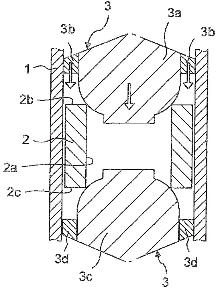
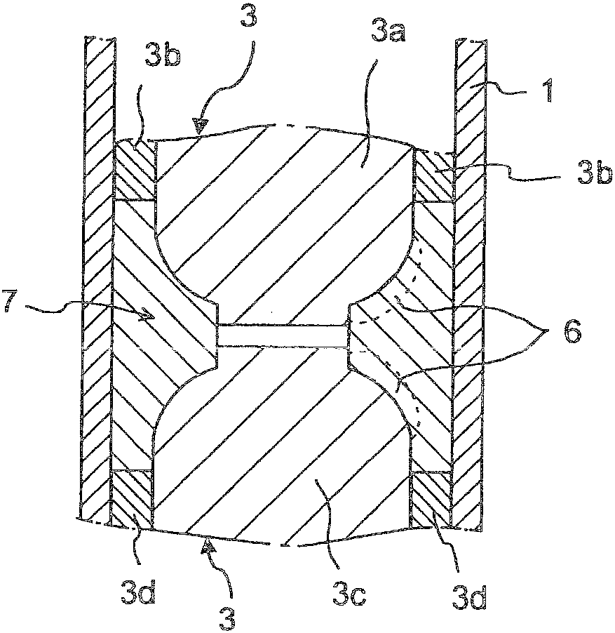
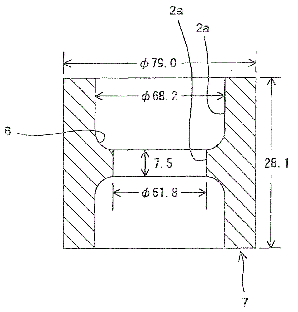
The present invention discloses a method of manufacturing a mechanical part excellent in rolling fatigue life. The machine part (7) has a rolling part (6) for rolling on an inner mirror surface rolling member of a ring-shaped base material subjected to cold forging. The method of the present invention has a step of cold forging by applying hydrostatic stress to the inner diameter surface (2a) of the annular processed base material where the rolling portion is desired to be formed, thereby forming the inner diameter surface (2a) of the annular processed base material The rolling part (6) for the rolling part is formed, and the inner diameter of the ring-shaped base material other than the rolling part (6) is enlarged to provide a ring-shaped rolling part (6) with excellent rolling fatigue life. Mechanical components (7). Improve the interface state between non-metallic inclusions contained in the steel material as the base material for annular processing and the steel material as the base material by plastic working, thereby enabling the manufacture of ring-shaped machine parts with rolling parts that have excellent rolling fatigue life in the inner diameter .

Description

[0001] Cross-reference of related applications [0002] This application claims priority based on Japanese Patent Application No. 2009-194962 filed on August 26, 2009 and Japanese Patent Application No. 2010-185927 filed on August 23, 2010, with reference to their entire disclosures. In the description of the invention of this application. technical field [0003] The present invention relates to the manufacture of mechanical parts made of steel such as bearings, gears, hub units, continuously variable transmissions, constant velocity connectors, and piston pins, and in particular to the manufacture of mechanical parts made of annular bodies that require good rolling fatigue life manufacture. Background technique [0004] In recent years, as the performance of various mechanical devices has increased, the use environment of mechanical parts and devices that require rolling fatigue life has become very severe, and there is a strong demand for improving the life and reliabili...

Claims


Application Information

Patent Timeline
Patent Type & Authority Patents(China)
IPC IPC(8): B21K1/04B21J5/00B21J5/08B21K21/16C21D7/10F16C33/64
CPCB21J5/00B21K1/04B21K21/16B21K23/04C21D7/10C21D8/10C21D9/40F16C19/184F16C33/64F16C2240/40C21D1/25C21D1/32B21J5/08
Inventor 中沟利尚桥本和弥
Owner SANYO SPECIAL STEEL COMPANY
Learn More