
Three-dimensional surface shaping of rotary cutting tool edges with lasers

A technology of rotating cutting tools and cutting edges, which is applied in the direction of rotating tools, tools for lathes, accessories of toolholders, etc., which can solve the problems of poor cutting edge quality, geometric shapes that cannot be defined point by point, high cost and processing time, etc. question

Active Publication Date: 2012-07-11
KENNAMETAL INC
View PDF17 Cites 16 Cited by
  • Summary
  • Abstract
  • Description
  • Claims
  • Application Information

AI Technical Summary

Problems solved by technology

These methods all have different types of disadvantages, such as poor cutting edge quality (EDM and ECG) and high costs and processing times (grinding)
A limitation also exists for all these methods in that free-form geometries cannot be defined point-by-point but must consist of defined surfaces generated by the surface generator (face of grinding wheel, wire electrode, etc.)

Method used


Image

  • Three-dimensional surface shaping of rotary cutting tool edges with lasers
  • Three-dimensional surface shaping of rotary cutting tool edges with lasers
  • Three-dimensional surface shaping of rotary cutting tool edges with lasers

Examples


Embodiment Construction

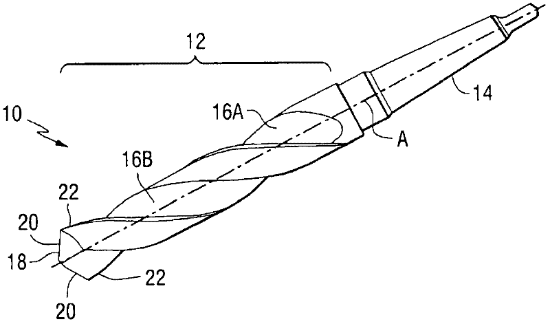
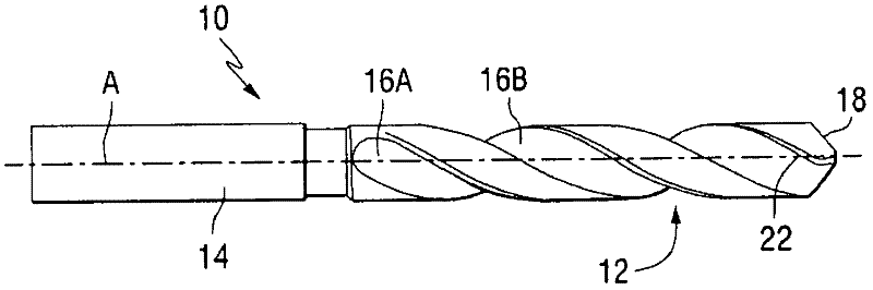
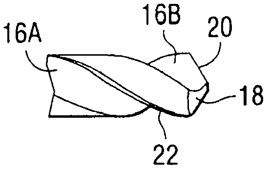
[0025] The laser forming method of the present invention can be used to form a plurality of cutting edges and surrounding contoured surfaces in a rotary cutting tool. As used herein, the term "rotary cutting tool" refers to a type of rotary tool used in chip evacuation machining. Examples of some types of rotary cutting tools that can be formed by the method of the present invention include: drills, drill tips, milling cutters, reamers, taps, graded drills, indexable drills, reamers, countersinks, orbitals Orbital tools, etc. The cutting edges of such tools can be made of very hard materials including: carbides; cermets such as cemented tungsten carbide; ceramics such as cubic boron nitride or alumina, polycrystalline diamond, and the like.

[0026] Figure 1 to Figure 4 Drill bits that can be made in accordance with the present invention are shown. However, it should be understood that any other type of rotary cutting tool having a similar type of cutting edge geometry is ...


PUM


Abstract

A method for forming the cutting edge (20, 22) and adjacent contoured surface (S) area of rotary cutting tools (10) utilizing a laser (50) to remove material from the cutting end (18) of the tool (10) to create a predetermined point-by-point geometry is disclosed. Relatively complex surface and edge geometries may be formed by directing a laser beam (L) toward the cutting end (18) of the tool (10) at an angle (theta) having a component (CN) that is normal to the surface (S) of the cutting end (18). The laser beam (L) is directed in multiple passes across the surface (S) of the cutting end (18) to remove material and form the desired cutting edge (20, 22) and adjacent three-dimensional contoured surface geometry (S).

Description

technical field [0001] The present invention relates to the formation of rotary cutting tool edges, and more particularly to the use of lasers to provide three-dimensional surface shaping of such cutting edges. Background technique [0002] It is well known that in machining it is desirable to have cutting edges that are harder than the material being machined. Throughout the evolution of the tool, this has progressed from stone to bronze, to iron, to carbon steel, to high speed steel, and then to hard carbide. In recent decades, this evolution has continued further with the introduction of ceramics (silicon nitride, alumina, etc.) and "superabrasive" materials such as polycrystalline diamond (PCD) and cubic boron nitride (CBN). Although these materials have greatly improved tool life in some materials by increasing hardness, wear resistance, and tolerance to cutting edge deformation, they have been difficult to apply to a wider tool range. This is due to the difficulties ...

Claims


Application Information

Patent Timeline
Patent Type & Authority Applications(China)
IPC IPC(8): B23K26/36B23K26/00B23B27/14B23K101/20
CPCB23K26/38B23K2201/002B23K26/4075B23K26/408B23K2101/002Y10T407/19B23B27/14
Inventor C·盖K·桑帕斯F·罗森伯格S·乔治
Owner KENNAMETAL INC
Learn More