Imaging radar method and system

a radar and imaging technology, applied in the field of high-resolution imaging radar, can solve the problems of limited use of imaging or radar applications, conventional time-reversal, and limited one-way distortion compensation proposed to date, and achieve the effects of improving resolution, high resolution, and extended virtual aperture (eva)

Inactive Publication Date: 2009-05-19
USA AS REPRESENTED BY THE SEC OF THE NAVY THE
View PDF7 Cites 62 Cited by
  • Summary
  • Abstract
  • Description
  • Claims
  • Application Information

AI Technical Summary

Benefits of technology

[0009]The invention overcomes limitations of conventional time-reversal using double-pass time-reversal imaging and photonic beam scanning. The radar beam is coherently focused not only on the target (as is the case with conventional phase conjugation) but also at the transmitter/receiver (Tx/Rx), satisfying the conjugate imaging requirements. The beam is then scanned along both azimuth and elevation directions using a photonic beam forming network to obtain an entire image. The time-reversal imaging is a combi

Problems solved by technology

However, the time-reversal proposed to date is limited to one-way distortion compensation.
This feature of target side-only focusing of the conventional time-reversal has limited its use for imaging or radar applications, which require compensation of di

Method used


Image

  • Imaging radar method and system
  • Imaging radar method and system
  • Imaging radar method and system

Examples


Embodiment Construction

[0019]Consider a monochromatic beam propagating through a linear lossless distorting medium in k direction

E1( r,t)=Re[ψ( r)·ei(ωt− k· r)]=Re[A1( r)·eiωt].

A1( r) reflects spatial modulation of information such as distortion and diffraction. Phase conjugation of E2( r,t) is defined as

E2( r,t)=Re[ψ•( r)·ei(ωt+ k· r)]=Re[A2( r)·eiωt],

where A2( r)=A1( r).

To get E2 from E1, we take the complex conjugate of the spatial part only, leaving the factor eiωt intact. This is equivalent to leaving the spatial part alone but reversing the sign of t. That's why phase conjugation is often called time-reversal.

However, traditional phase conjugation works for only monochromatic waves and has limited applications, while time-reversal works for arbitrary waveforms.

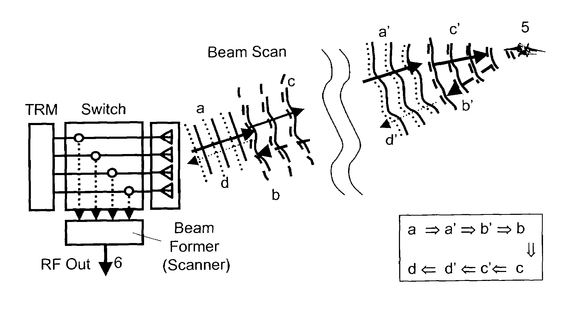
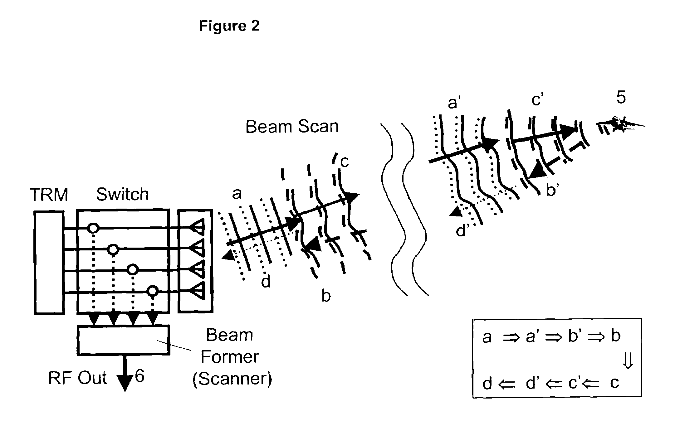
[0020]Referring now to FIG. 2 and Table 2, the operational principle of the time-reversed double-passed extended virtual aperture (DPEVA) radar is described below in Table 2, noting that the “BEAM” is as shown in FIG. 2 with the corresponding ...


PUM


Abstract

A time-reversal imaging radar system for acquiring an image of a remote target includes an antenna array having a plurality of spaced-apart antennas, and a transceiver coupled to the antenna array for alternately transmitting a radar signal via the antenna array toward the target and for receiving target-reflected radar signals. The transceiver includes means for multiple-pass time-reversing the transmitted and received radar signals whereby coherent beam focusing is realized at both the target and at the receiver to thereby enhance the resolution of the acquired target image.

Description

FIELD OF THE INVENTION[0001]This invention relates generally to high resolution imaging radar. In particular, the invention relates to a time-reversed scanning imaging radar with an enhanced-resolution acquired target image.BACKGROUND OF THE INVENTION[0002]Time-reversal (sometimes referred to as phase-conjugation) has characteristics that make it highly attractive for radar applications. These include automatic tracking of moving targets and self-focusing, regardless of atmospheric turbulence without a need for any prior knowledge or iterative adaptive processing. However, the time-reversal proposed to date is limited to one-way distortion compensation. The operation of the conventional single-pass time-reversal radar is shown in FIG. 1 and is as follows:[0003]TABLE 1Operational principle of conventional single-pass time-reversal.BEAMBEAM CHARACTERISTICSa′A pilot beam illuminates the area that includes an intendedtarget.b′Part of the beam is reflected from the target. Its wavefront ...

Claims


Application Information

Patent Timeline
IPC IPC(8): G01S13/02G01S13/89H01Q3/00
CPCG01S7/282G01S13/426H01Q3/30H01Q3/40G01S2013/0227G01S2013/0254
Inventor CHOE, JOON YPAEK, EUNG GI
Owner USA AS REPRESENTED BY THE SEC OF THE NAVY THE
Why Eureka
Try Eureka