Method of applying atomic layer deposition coatings onto porous non-ceramic substrates

A non-ceramic, substrate-based technology for flow-through atomic layer deposition

Inactive Publication Date: 2012-07-11
3M INNOVATIVE PROPERTIES CO
View PDF14 Cites 3 Cited by
  • Summary
  • Abstract
  • Description
  • Claims
  • Application Information

AI Technical Summary

Problems solved by technology

[0005] The present invention solves the diffusion problem mentioned above by...

Method used


Image

  • Method of applying atomic layer deposition coatings onto porous non-ceramic substrates
  • Method of applying atomic layer deposition coatings onto porous non-ceramic substrates
  • Method of applying atomic layer deposition coatings onto porous non-ceramic substrates

Examples


example

[0044] Objects and advantages of this invention are further illustrated by the following examples, but the particular materials and amounts thereof recited in these examples, as well as other conditions and details, should not be construed to unduly limit this invention.

[0045] Method for measuring the surface energy of a sample

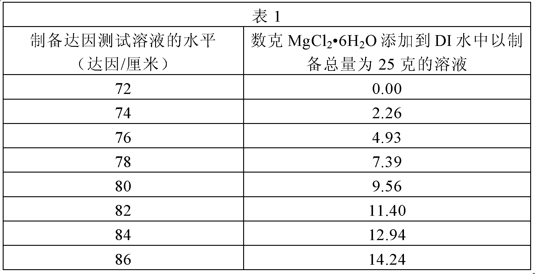
[0046] Various samples of ALD-coated porous non-ceramic substrates are described below in conjunction with the Examples. When the surface energy of a sample is discussed, its readings are obtained in the following manner: Various levels of dyne test solutions are obtained. Solutions according to ASTM standard D-2578 were purchased from Jemmco, LLC (Mequon, WI) at levels ranging from 30 to 70 dynes / cm. through the MgCl shown in Table 1 2 ·6H 2 The amount of O was mixed with sufficient deionized water to make a solution ranging in level from 72 to 86 dynes / cm to make a total of 25 grams of solution.

[0047]

[0048] Using these dyne test so...

example 1

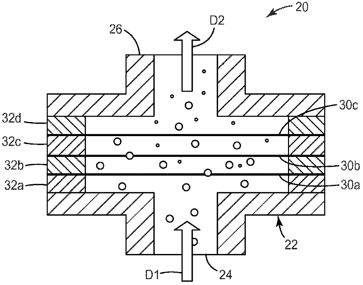
[0068] Each double-sided flange of the reactor was used to support a disc cut from the porous polypropylene film of Substrate A above. The disc was attached by attaching the disc to a copper washer with double sided tape and placing the copper washer into the normal sealing position between the 6 inch (15.24 cm) diameter ConFlat Double side flanges. Each of the three samples of the sheet was placed inside the reactor. As the reactors are sealed together and secured to form the reactor body, the ConFlat double sided flange seals pass through the membrane and form a hermetic seal with conventional copper gasket sealing mechanisms. The sealed reactor will also help to hold the membrane in place and seal the edges of the membrane to prevent any reactive gases from bypassing the membrane.

[0069] The reactor with the membrane in place is then attached to the vacuum and gas handling system as described above. The first reactive gas supply tank was filled with 97% trimethylaluminu...

example 2

[0074] The experiment was generally carried out according to the procedure of Example 1, except that the substrate used was substrate B instead of substrate A; the reactor, first and second inlet lines, and purge lines were heated to 60 °C by a heater, and repeated is 20 instead of 35. After 20 iterations had been performed, the reactor was opened and the surface energy of each of the three wafers of Sample B was evaluated. Each disc has a surface energy in excess of 86 dynes / cm, indicating a high degree of hydrophilicity.


PUM


Abstract

A method of depositing a conformal coating on a porous non-ceramic substrate requires reactive gases to flow through the substrate so as to leave a conformal coating behind. The process can be used to leave a hydrophilic surface on the interior pores of the substrate, even when the substrate is of a naturally hydrophobic, e.g., olefinic material. The method can be used in a roll-to-roll process, or in a batch process. In some convenient embodiments of the latter case, the batch reactor and the conformally coated substrate or substrates can together go on to be come part of the end product, e.g., a filter body and the filter elements respectively.

Description

[0001] Cross references to related patent applications [0002] This application claims the benefit of US Provisional Patent Application Nos. 61 / 244,713 and 61 / 244,696, both filed September 22, 2009, the disclosures of which are incorporated herein by reference in their entirety. technical field [0003] The present invention relates to the preparation of treated porous non-ceramic substrates, and more particularly to the flow through atomic layer deposition process for this purpose. Background technique [0004] The atomic layer deposition (ALD) method was originally developed for thin film electroluminescent (TFEL) flat panel displays. Interest in ALD has increased significantly in recent years, focusing on silicon-based microelectronics (wafers), due to its ability to fabricate very thin, conformal films and to control the composition and thickness of these films at the atomic level. ALD (due to its own limited, sequential surface reaction process) is also known for its...

Claims


Application Information

Patent Timeline
IPC IPC(8): C23C16/455C23C16/00H01L21/205C23C16/54C23C16/30C23C16/06
CPCD06M11/45C23C16/45546C23C16/45525D06C29/00C23C16/403C08J2201/038D06M11/58D06M23/005C23C16/45555C23C16/045H01L21/02532D06M11/36H01L21/02422C08J9/365H01L21/02428D06M11/53Y10T428/1362Y10T428/1376Y10T428/249958Y10T442/2861C23C16/545
Inventor 比尔·H·道奇
Owner 3M INNOVATIVE PROPERTIES CO
Why Eureka
Try Eureka