Malodorous gas treatment system and method thereof

A malodorous gas and treatment system technology, which is applied in the direction of separation methods, chemical instruments and methods, and air quality improvement, can solve the problems of unsuitable high-concentration malodorous gas purification treatment, etc., and achieves compact structure, simple operation and maintenance, and simple structure Effect

Inactive Publication Date: 2012-07-18
苏州苏净环保科技有限公司
View PDF4 Cites 16 Cited by
  • Summary
  • Abstract
  • Description
  • Claims
  • Application Information

AI Technical Summary

Problems solved by technology

[0009] The contribution of the above-mentioned patent mainly lies in the integration of humidification and biological reaction, which solves the problem of acidification and drying of the filter bed that plagues the application

Method used


Image

  • Malodorous gas treatment system and method thereof
  • Malodorous gas treatment system and method thereof

Examples


Embodiment 1

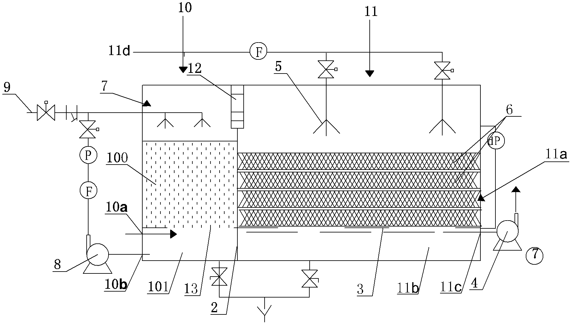
[0033] This embodiment provides a malodorous gas treatment system. Such as figure 1 As shown, the malodorous gas treatment system mainly includes a reaction vessel, which is divided into a first reaction chamber 10 and a second reaction chamber 11 side by side by a partition plate 2 placed therein, at the top of the partition plate 2 and the reaction vessel There is a gap 12 connecting the first reaction chamber 10 and the second reaction chamber 11 therebetween.

[0034] The first reaction chamber 10 is provided with a porous plate 13 , which divides the first reaction chamber 10 into a chemical washing humidity control area 100 located above and a detergent storage area 101 located below. A waste gas inlet 10a is provided on the upper part of the side wall of the first reaction chamber 10 where the detergent storage area 101 is located, and a detergent outlet 10b is provided below the waste gas inlet 10a. The malodorous gas treatment system of this example also includ...

Embodiment 2

[0039] This embodiment provides a method for applying the malodorous gas treatment system of Embodiment 1 to process malodorous gas containing hydrogen sulfide and ethanethiol.

[0040] The malodorous gas containing hydrogen sulfide and ethanethiol enters the upper part of the detergent storage area 101 through the waste gas inlet 10a, and enters the chemical washing humidity control area 100 through the perforated plate 13. The detergent in the detergent storage area 101 is sprayed on the upper part of the chemical washing humidity control area 100 through the detergent circulation pump 8, and the detergent is a weakly alkaline agent. The upward exhaust gas is mixed with the downward detergent, most of the hydrogen sulfide in the exhaust gas is removed, and the humidity is adjusted. The humidity-adjusted exhaust gas directly enters the biological reaction zone 11 a through the gap 12 . In the biological reaction zone 11a, after the waste gas passes through multi-layers a...


PUM


Abstract

The invention discloses a malodorous gas treatment system and a method thereof, wherein the treatment system comprises a reaction vessel, the reaction vessel is separated into a first reaction chamber and a second reaction chamber which are positioned side by side through a clapboard, a gap is left between the clapboard and the top of the reaction vessel, and a waste gas inlet and a detergent outlet are arranged on the side of the lower part of the first reaction vessel; the malodorous gas treatment system further comprises a spray system and a detergent circulating pump which are arranged at the upper part of the first reaction chamber, a perforated plate is arranged at the lower part of the second reaction chamber and separates the second reaction chamber into a bioreaction area and a nutrient solution storage area, a purified-gas outlet is arranged on the side wall of the nutrient solution storage area in the second reaction chamber, and a draught fan is arranged at the purified-gas outlet; and a layer or a plurality of layers of inert fillers arranged on the perforated plate are contained in the bioreaction area, wherein microorganisms grow on the inert fillers in an attaching way. The system has a compact structure, is suitable to treatment of different kinds of malodorous gases of different concentrations and loads. The method is economic and efficient.

Description

technical field [0001] The invention belongs to a device and a method for treating malodorous gas. Background technique [0002] In order to prevent and avoid the impact of the odor of sewage treatment plants on the lives of surrounding residents, some developed countries have successively formulated some specific regulations. For example, Germany stipulates that no living measures shall be built within 300m outside the boundaries of urban sewage plants. If this requirement cannot be met, sewage treatment Necessary measures must be taken in the factory to prevent the spread of odor. my country has built more than 2,800 sewage treatment plants and tens of thousands of supporting sewage pumping stations. Most of them are distributed in large and medium-sized cities, and some are difficult to avoid residential areas, so their odor problems should also be solved. There are two main types of pollution control for malodorous gases: source control and post-collection treatment. ...

Claims


Application Information

Patent Timeline
IPC IPC(8): B01D53/75B01D53/78B01D53/84
CPCY02A50/20
Inventor 朱国营王家骅马楫刘立贵刘汉鹏杜永祥卞广荣范佳华尹方平黄东
Owner 苏州苏净环保科技有限公司
Why Eureka
Try Eureka