
Automatic laser engraving and code reading equipment for oil spraying nozzle

A technology of laser engraving and fuel injectors, applied in engraving, decorative art, processing models, etc., can solve the problem that mass production cannot be monitored effectively in real time, the model, specification and production information cannot be well controlled, and cannot be one-to-one Correspondence and other issues

Active Publication Date: 2012-07-18
KERUI AUTOMATION TECH SUZHOU
View PDF9 Cites 11 Cited by
  • Summary
  • Abstract
  • Description
  • Claims
  • Application Information

AI Technical Summary

Problems solved by technology

[0003] At present, the production line includes 3 independent station equipment (each station is an independent equipment), that is, assembly station equipment, laser engraving station equipment and code reading station equipment, which will often result in model, specification and production information, etc. It cannot be well controlled, and cannot be matched one-to-one; in addition, the operator may take the wrong material, or even confuse the specifications of the material; because manual work is difficult, inefficient, and error-prone, and the station There are many, CPK is less than 1.0, and UPH is only a little over 200
Due to low efficiency, low pass rate, cumbersome operation, individual processing and measurement, etc., it is far from meeting the actual quality requirements, and batch production cannot be monitored effectively in real time.

Method used


Image

  • Automatic laser engraving and code reading equipment for oil spraying nozzle
  • Automatic laser engraving and code reading equipment for oil spraying nozzle
  • Automatic laser engraving and code reading equipment for oil spraying nozzle

Examples


Embodiment Construction

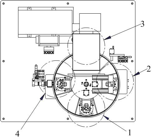
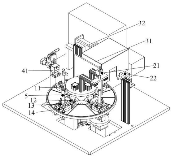
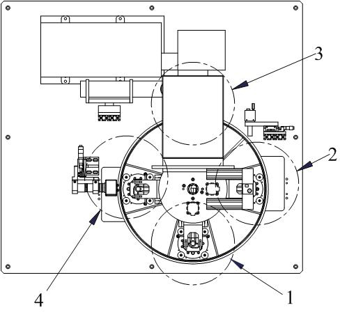
[0016] like figure 1 As shown, the automatic laser engraving and code reading equipment for fuel injectors includes a frame and an index plate installed on the frame. The index plate is equipped with a loading and unloading station device 1, an ID identification station device 2, Laser engraving station device 3 and two-dimensional code detection station device 4, such as figure 2 As shown, the loading and unloading station device 1 includes a clamping mechanism 12, a cylinder 11 and a fixed block 13, the piston rod of the cylinder 11 is connected to the clamping mechanism 12, and the fixed block 13 is arranged under the clamping mechanism 12, and the fixed block 13 passes The positioning rotation axis is installed on the lifting rotating platform 14, and the lifting rotating platform 14 is installed on the lifting platform lifting device;

[0017] The ID identification station device 2 includes a CCD camera 21 located directly above and a CCD camera 22 located on the side; ...


PUM


Abstract

The invention relates to automatic laser engraving and code reading equipment for an oil spraying nozzle. An indexing disc is provided with a loading and unloading station device, an ID (identity) recognizing station device, a laser engraving station device and a two-dimensional code detecting station device; the loading and unloading station device comprises a clamping mechanism, an air cylinder and a fixed block, wherein the piston rod of the air cylinder is connected with the clamping mechanism in a driving way, the fixed block is arranged below the clamping mechanism and on a lifting rotating platform, and the lifting rotating platform is arranged on a lifting-platform lifting device; the ID recognizing station device comprises two CCD cameras, wherein one CCD camera is arranged over the ID recognizing station device, and the other CCD camera is arranged on the side surface of the ID recognizing station device; the laser engraving station device comprises a laser engraving machine and an exhausting system, wherein the exhausting is arranged on the side surface of the laser engraving machine; and the two-dimensional code detecting station device comprises a camera and an industrial personal computer, wherein the camera is connected with the industrial personal computer. The automatic laser engraving and code reading equipment has high processing qualification rate and high efficiency and can monitor the production process on line in real time.

Description

technical field [0001] The invention relates to an automatic laser engraving and code reading equipment for a fuel injection nozzle. Background technique [0002] The fuel injector of the electronically controlled high-pressure diesel direct injection system is the most important key core part, which requires traceability to make the diesel engine cleaner, more efficient and more economical. [0003] At present, the production line includes 3 independent station equipment (each station is an independent equipment), that is, assembly station equipment, laser engraving station equipment and code reading station equipment, which will often result in model, specification and production information, etc. It cannot be well controlled, and cannot be matched one-to-one; in addition, the operator may take the wrong material, or even confuse the specifications of the material; because manual work is difficult, inefficient, and error-prone, and the station There are many, CPK is less ...

Claims


Application Information

Patent Timeline
IPC IPC(8): B44B1/00B44B3/00
Inventor 周锐张军挺朱德华
Owner KERUI AUTOMATION TECH SUZHOU
Learn More